 TEL +86-13923172919
EV Battery Pack and Automotive Plastics: High-Frequency Welding Limits
A tier-1 automotive supplier setting up an assembly line for EV battery HF welding faces a critical engineering hurdle: creating airtight, flame-retardant insulation barriers around cell modules without introducing thermal stress or mechanical vibration that could damage internal micro-electronics. Standard heat sealing struggles with cycle speed and thermal damage on thick polymer layers, while ultrasonic welding is geographically limited by horn size and risks shaking delicate wire bonds within battery cells.
High-frequency (HF) welding—also known as radio-frequency (RF) welding—provides an alternative by generating internal dielectric heat strictly within the joint area. However, HF welding for EV battery modules and automotive interior plastics is not a universal solution. Successfully integrating this technology requires a precise understanding of material dielectric properties, mechanical pressure limits, tooling configuration, and electrical safety boundaries.
Technical Mechanism & Material Compatibility Boundaries
HF welding operates by passing alternating electromagnetic energy (typically standard industrial 27.12 MHz) between two metal electrodes. The alternating electric field causes polar molecules within the polymer to realign millions of times per second, generating uniform friction heat throughout the material matrix.
| Parameter | Operating Range / Limit | Engineering Significance |
| Electrode Pressure | 40 to 60 PSI (2.7 to 4.1 bar) | Ensures intimate interfacial contact and prevents arcing or material thinning under high electromagnetic gradients. |
| Welding Duration | 3.0 to 5.0 seconds | Minimizes thermal degradation while achieving complete molecular interdiffusion across the joint interface. |
| Cooling Phase | ~20% of welding duration under sustained clamping pressure | Prevents elastic spring-back and residual stress fracture in hermetic EV battery enclosure seals. |
| Dielectric Breakdown Voltage | > 15 kV/mm | Maintains structural insulation integrity for high-voltage (400V to 800V+) battery architectures. |
Dielectric Loss Factor Requirements
The physical limit of HF welding depends entirely on the polymer’s dielectric loss factor ($\varepsilon” = \varepsilon’ \cdot \tan\delta$).
- Directly Weldable Polymers: Polyvinyl chloride (PVC), thermoplastic polyurethane (TPU), polyurethane-coated fabrics, and specialized polar-modified PETG blends. These materials possess high dipole moments, allowing rapid fusion within 2.0 to 4.0 seconds.
- Non-Weldable / Challenging Polymers: Pure polyolefins such as polypropylene (PP), high-density polyethylene (HDPE), and polycarbonate (PC) have negligible loss factors. They cannot absorb HF energy directly under normal operating conditions.
- EV Composite Interfaces: Structural battery module trays and outer cell covers often rely on glass-fiber-reinforced PP or PA66 for mechanical stiffness. Do not attempt direct HF welding on unmodified PP or HDPE housings without a polar co-extruded film or intermediate TPU tie-layer. Doing so will cause zero energy absorption, leading to unsealed joints and production scrap.
Engineering Boundaries and Operating Limits
When sealing battery pack insulation sheets, busbar protective wraps, or fluid cooling channels, machine operators and process engineers must stay within controlled technical thresholds to prevent structural failure or arc damage.
| Machine Type | Core Operating Advantage | Typical Automotive / EV Application |
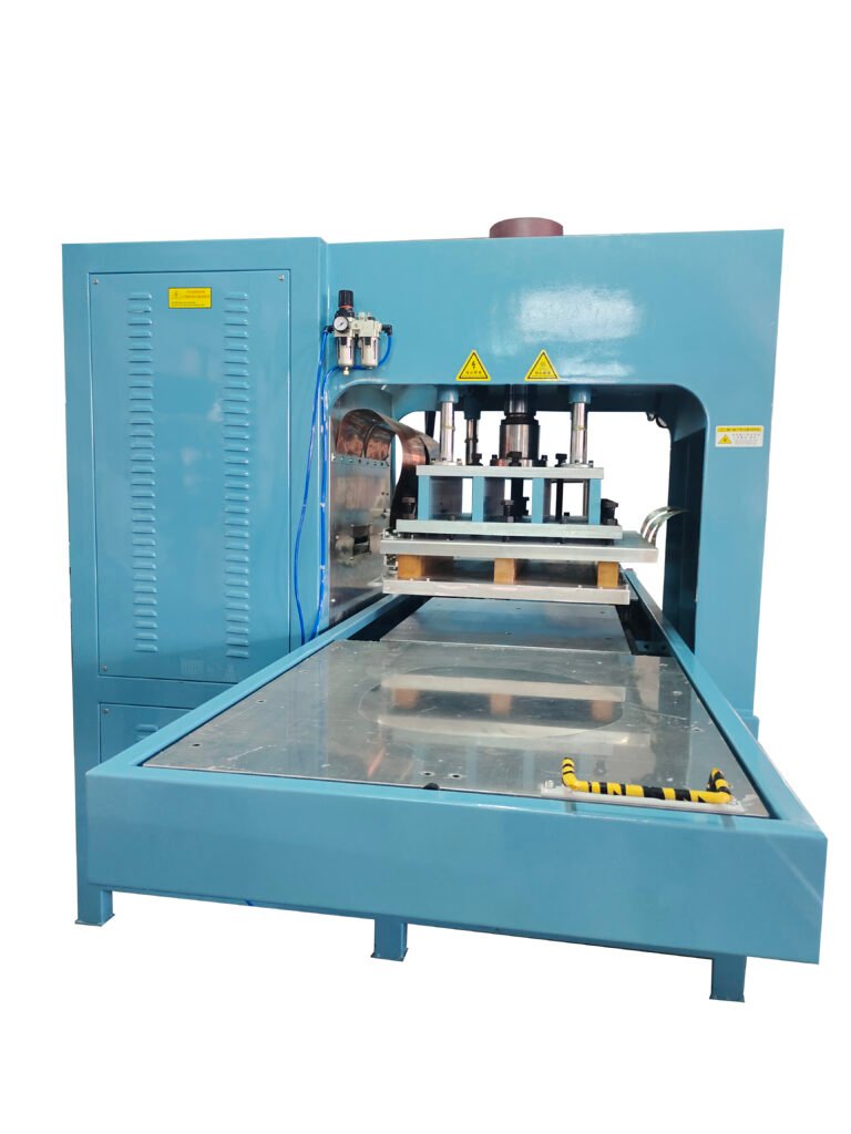
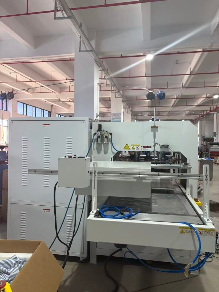
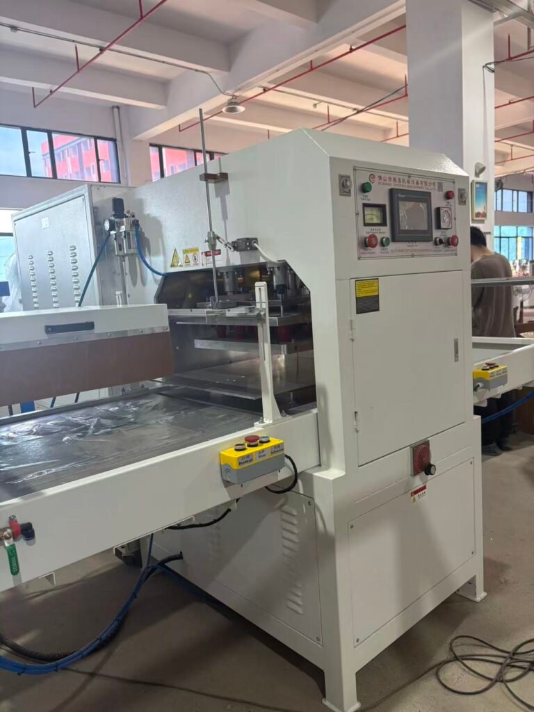
| Push-Plate HF Welder | Flat bed, high positioning room for wide geometry layers | Large battery insulation sheets, trunk liners, door panel covers |
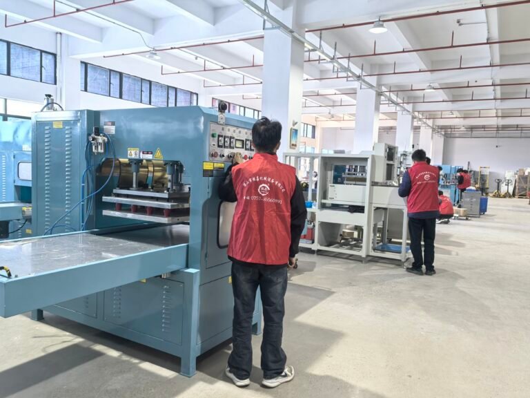
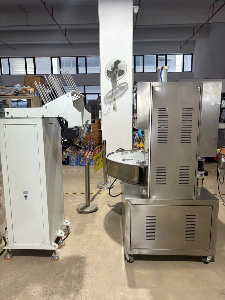
| Automatic Rotary Table HF Machine | Multi-station: Operator loads station A while machine welds station B | High-volume battery module sleeves, wire harness seals, fluid pouches |
| Hydraulic High-Power HF Welder (12KW+) | High force output, robust frame for wide surface area welds | Multi-layer thick TPU/PVC bladders, heavy-duty liquid cooling bladders |
1. Pressure and Clamping Boundaries
- Nominal Operating Pressure: Clamping force must remain strictly between 40 and 60 PSI (2.7 to 4.1 bar).
- Under-pressurization Hazard: Insufficient pressure leaves microscopic air pockets within the joint seam. When high-voltage fields pass through the battery pack, these micro-voids suffer dielectric breakdown, ruining the sealing integrity.
- Over-pressurization Hazard: Excessive pressure squeezes molten polymer out of the joint zone, thinning the insulating seam below required electrical creepage distances.
2. Arc Suppression and Voltage Limits
- High-voltage spark damage is the single largest threat to custom welding dies and thin battery pouch materials.
- Machines must be equipped with ultra-fast electronic arc suppressors (thyristor-driven circuits) that kill HF energy within microseconds when current spikes occur.
- Welding dies must feature smooth, radiused edges (minimum 0.5 mm radius). Sharp corners concentrate electrical field lines, triggering catastrophic arcing that damages both the tool and the EV component.
3. Cooling Phase under Clamping Pressure
- Never release mechanical clamping pressure immediately after the HF power shuts off.
- The polymer must undergo a cooling hold under pressure—typically 20% to 30% of the total welding cycle duration—to allow molecular re-crystallization. Releasing pressure prematurely causes spring-back, internal stress concentration, and subsequent pinhole leaks under vehicle thermal cycling (-40°C to +85°C).
Machine Structure Selection for Automotive Lines
Matching the equipment structure to your target throughput and part geometry determines whether your production line achieves target cycle times.
+------------------------+------------------------------------+---------------------------------------+
| Machine Type           | Core Operating Advantage           | Typical Automotive / EV Application   |
+------------------------+------------------------------------+---------------------------------------+
| Push-Plate HF Welder   | Flat bed, high positioning room    | Large battery insulation sheets,      |
|                        | for wide geometry layers           | trunk liners, door panel covers       |
+------------------------+------------------------------------+---------------------------------------+
| Automatic Rotary Table | Multi-station: Operator loads station A | High-volume battery module sleeves,  |
| HF Machine             | while machine welds station B      | wire harness seals, fluid pouches     |
+------------------------+------------------------------------+---------------------------------------+
| Hydraulic High-Power   | High force output, robust frame    | Multi-layer thick TPU/PVC bladders,   |
| HF Welder (12KW+)      | for wide surface area welds        | heavy-duty liquid cooling bladders    |
+------------------------+------------------------------------+---------------------------------------+
Technical Tooling and Custom Mold Integration
An HF welding machine cannot operate as a standalone unit; it relies entirely on the precision of the high-frequency welding die (electrode).
- Tooling Material: High-grade brass or specialized aluminum alloys are required for optimal electrical conductivity and dimensional stability under repeated heating.
- 3D Seam Alignment: For EV battery pouch surrounds or non-planar automotive interior panels, the upper electrode and lower fixture plate must be precision CNC-milled to maintain parallel contact across the entire perimeter. Misalignment of as little as 0.05 mm causes uneven current density, resulting in burnt edges on one side and unsealed material on the other.
- Custom Tooling + Proofing: When introducing new flame-retardant TPU or composite insulating films, machine configuration and die manufacture must be addressed simultaneously. Manufacturers should submit exact material samples for sample proofing to calibrate weld seam width, tear-seal line depth, and RF power settings prior to full production.
Operational Safety Boundaries
Given the combination of high radio frequencies, pneumatic/hydraulic pressures, and internal high voltages, strict workplace safety practices must be enforced on the factory floor.
- MUST verify that all cabinet shielding doors and grounding chains are securely attached before turning on the high-voltage generator.
- MUST install dual palm start buttons requiring simultaneous operator activation to keep hands clear of the clamping area.
- PROHIBITED: Never operate the HF equipment with safety guards removed or arc-suppression sensitivity bypassed.
- PROHIBITED: Never place hands between upper and lower electrodes during machine arm descent or RF discharge. High-frequency electromagnetic energy causes immediate, deep thermal burns within body tissue.
- NEVER perform maintenance or mold alignment while the main electrical cabinet is energized. Lockout/Tagout (LOTO) protocols must be strictly enforced.
Factory Power and Equipment Support in Regional Deployments
When deploying HF welding machinery for automotive production in overseas or regional factories (such as Southeast Asian manufacturing hubs):
- Power Supply Verification: Standard heavy-duty HF welding machines typically require a 380V / 3-Phase / 50Hz electrical supply. Always confirm local plant line voltage, phase stability, and grounding capacity prior to machine ordering, as voltage fluctuations degrade RF field stability.
- Air Supply Quality: Pneumatic-driven heads require dry, filtered compressed air (minimum 6 bar continuous pressure). Moisture in air lines damages pneumatic cylinders and causes erratic electrode down-speed.
- Technical Support: Prioritize suppliers capable of providing comprehensive video-assisted troubleshooting, detailed electrical schematics, remote technical support, and accessible spare parts (e.g., spark tubes, vacuum tubes, relays, and pneumatics) to prevent extended line downtime.