 TEL +86-13923172919
Inside a Solid State RF Welder: Generator and Matching
A production manager in a high-volume blister packaging facility often faces a recurring frustration: inconsistent seal strength between the first hour of the shift and the last. In traditional high-frequency equipment, this drift is frequently caused by the aging and thermal instability of vacuum tubes. Transitioning to a solid state RF welder addresses these fluctuations at the source by replacing the oscillating tube with semiconductor-based power components.
Understanding the internal architecture of a solid state system is essential for technical buyers in Southeast Asia who are evaluating long-term operational costs and output quality. Unlike older technology, a solid state HF generator utilizes transistors to convert factory power into the high-frequency energy required for molecular friction welding. This shift in hardware changes how the machine handles power stability, energy consumption, and the critical process of impedance matching.
The Role of the Solid State HF Generator
The heart of a solid state RF welder is its power supply. Traditional machines rely on a vacuum tube to generate the 27.12MHz or 40.68MHz frequency. These tubes require a warm-up period, consume significant energy even when idling, and their output power degrades over thousands of hours. In contrast, a solid state HF generator uses MOSFET or IGBT modules that are ready for immediate operation.
This semiconductor approach allows for precise control over the HF welding power supply. Because the power is managed digitally, the machine can maintain a constant output even if the factory voltage fluctuates. For facilities in regions where power grid stability varies, this prevents the ‘weak weld’ issues that lead to product rejects. Furthermore, the solid state generator is significantly more energy-efficient, as it does not require the high filament voltage needed to heat a vacuum tube.
RF Matching Network and Power Stability
Generating the high-frequency signal is only half of the process; the energy must be efficiently transferred to the material through the mold. This is where the RF matching network becomes vital. In any HF welding application, the ‘load’ (the material and the mold) has a specific electrical impedance. If the impedance of the generator does not match the impedance of the load, energy is reflected back to the source rather than being used for welding.
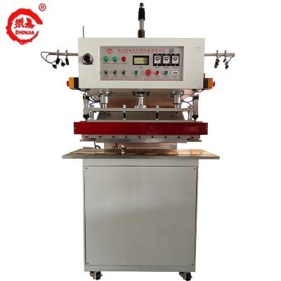
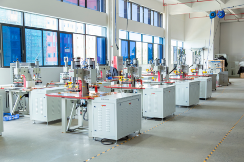
A solid state RF welder typically features an automated or highly stable matching network. This system ensures that the maximum amount of power reaches the welding zone. When working with materials like PET or PETG, which have a narrow processing window, the ability of the matching network to maintain stability throughout the welding cycle is the difference between a clean seal and a burnt edge. For complex multi-station setups, such as the ZJ-15K-ADRB Four-Station HF Welding Machine, this stability ensures that every station produces identical results regardless of minor variations in mold temperature.
Internal Differences: Solid State vs. Vacuum Tube
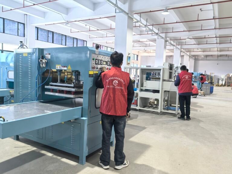
When comparing these two technologies, the differences are found in maintenance requirements and physical footprint. A vacuum tube machine requires a large high-voltage transformer and a cooling blower for the tube itself. A solid state system is more compact and modular. If a power module fails in a solid state generator, it can often be replaced individually, whereas a blown vacuum tube requires a total replacement of the most expensive component in the machine.
However, it is important to note that machine selection and mold design need to be considered together. A solid state RF welder provides the power, but the mold acts as the electrode. If the mold is poorly machined or incorrectly aligned, even the most advanced solid state HF generator cannot compensate for the resulting uneven pressure or arcing. For new or complex product structures, we always recommend sample testing to verify how the specific material responds to the solid state power curve.
Operational Safety and Power Requirements
While solid state technology is more efficient, it still involves high-voltage and high-frequency energy. Operators must adhere to strict safety boundaries to prevent injury and equipment damage. Before any operation, confirm your factory power supply matches the machine requirements (typically 380V, 3-phase). Never attempt to modify the high-voltage or control systems without authorization.
- Maintenance or inspection must only be performed after executing power-off and isolation procedures.
- Never treat high-frequency equipment as ordinary low-voltage machinery.
- Do not reach into dangerous moving areas while the pneumatic or hydraulic systems are active.
- Operation with safety guards removed is strictly prohibited.
For manufacturers in Southeast Asia, the choice between a traditional tube machine and a solid state RF welder often comes down to the specific application. Vacuum tube machines remain a robust choice for very high-power applications or where initial capital expenditure is the primary constraint. Solid state models are better suited for precision medical packaging, eco-friendly plastics like PETG, and environments where energy costs and consistent power stability are the priorities. To determine the exact configuration for your production line, please confirm with our team regarding material compatibility and mold design.
Before production: installation and safety checks
Before the first production run, confirm the mechanical, electrical and process conditions with the responsible engineer. Record the approved settings and keep them with the machine record.
- Confirm the local supply voltage, phase and frequency against the machine nameplate.
- Verify protective earth and equipotential bonding before energising the machine.
- Check that guards, emergency stops and two-hand controls operate correctly.
- Inspect cables, plugs, pneumatic lines and cooling connections for damage.
- Confirm the die or electrode is clean, flat and correctly aligned to the platen.
- Set pressure, weld time and cooling time from a approved sample, not from guesswork.
- Run a test weld on scrap material of the same grade and thickness as production stock.
- Inspect the test weld for arcing, burn-through, incomplete fusion and distortion.
- Record the approved parameters and restrict changes to authorised personnel.
- Train the operator on loading, unloading, emergency stop and lockout procedures.
For a broader selection framework, see the blister packaging machine selection guide.