Solid State HF Welding Machine Maintenance: Why It Costs Less to Run and What Still Needs Checking Every 12 to 18 Months
A solid state HF welding machine fundamentally changes the maintenance equation. There is no oscillator tube to replace. No filament transformer to burn out. No high-voltage rectifier stack to fail. The components that dominated the service schedule of a tube machine simply do not exist in a solid state generator. This is the primary reason solid state machines carry a lower solid state welder maintenance cost over their operating life.
Lower maintenance does not mean zero maintenance. Solid state machines substitute one set of service requirements for another. The IGBT modules, DC rectifiers, water cooling circuits, and DC link capacitors all require periodic inspection and eventual replacement. Ignoring these components until failure converts a manageable service event into an expensive emergency.
This guide explains what solid state RF welder upkeep actually involves. It covers the components that still need checking, the recommended 12 to 18-month service interval, and the operating cost advantages that make solid state machines the preferred choice for new installations.

What Solid State Machines Eliminate from the Maintenance Schedule
Understanding what you no longer need to service clarifies why solid state HF welding machine maintenance costs less. A tube machine devours operator attention across multiple subsystems that solid state technology renders obsolete.
The oscillator tube itself is the largest single maintenance item on a tube machine. At $2,000 to $8,000 per replacement and 5,000 to 8,000 hours of typical service life, the tube alone accounts for a significant operating cost per hour. Solid state machines have no oscillator tube. The RF power generation uses IGBT or MOSFET modules rated for the designed life of the machine.
The filament supply circuit disappears entirely. Tube machines require a dedicated filament transformer and associated wiring to heat the tube cathode. This circuit runs at high current and low voltage. Connections oxidize and loosen over time. Solid state machines eliminate this entire subsystem.
The high-voltage DC power supply in a tube machine operates at 5,000 to 8,000 volts. The transformer, rectifier stack, and filter capacitors at these voltages demand specialized insulation testing and careful cleaning to prevent flashover. Solid state generators operate the DC bus at much lower voltages, typically 300 to 800 volts. The lower voltage reduces insulation stress and eliminates the dust-attracting electrostatic fields that plague tube cabinet interiors.
Components That Still Require Periodic Service
A solid state RF welder upkeep program focuses on a different set of components. These items do not demand attention every week, but they do require scheduled inspection and eventual replacement.
IGBT Power Modules
The IGBT modules are the switching elements that generate RF output. They are solid state devices with no wear-out mechanism under normal operation. However, they are mounted on heatsinks that depend on forced-air or water cooling. The thermal interface compound between the module base and the heatsink degrades over years. It dries out, loses thermal conductivity, and allows the module to run hotter than intended.
Inspect IGBT modules at the 12 to 18-month service interval. Check that all mounting screws remain at the specified torque. Remove one module if practical and examine the thermal compound. Replace the compound if it appears dry, cracked, or has pulled away from the surfaces. Clean both the module base and the heatsink face thoroughly before applying fresh compound. A tube of thermal paste costs a few dollars. An overheated IGBT module costs hundreds and stops production.
DC Rectifier and Capacitor Bank
The incoming AC mains power converts to DC through a rectifier bridge. This DC bus powers the IGBT inverter stage. The rectifier modules handle the full machine input current. Their connections carry high current and are subject to thermal cycling.
Inspect the rectifier module connections at each service interval. Tighten all screw terminals to the specified torque. Look for discoloration of the terminal insulation, which indicates overheating. Measure the forward voltage drop of each diode in the bridge if the rectifier design permits individual diode access. A diode with increased forward drop generates excess heat and will eventually fail.
The DC link capacitor bank smooths the rectified voltage and provides peak current during the RF cycle. Electrolytic capacitors have a finite life. The life rating, typically 5,000 to 10,000 hours at rated temperature, depends strongly on operating temperature. Capacitors running 10°C below their rated temperature can double their service life.
Inspect capacitors visually at each service interval. Look for bulging of the pressure relief vent, leakage of electrolyte, or discoloration of the capacitor case. Measure capacitance and equivalent series resistance with a proper capacitor tester. Compare the readings to the capacitor specification. Replace any capacitor that measures more than 20% below rated capacitance or whose ESR exceeds the manufacturer’s maximum limit by 50%. A capacitor bank that degrades unevenly stresses the remaining capacitors and accelerates the failure of the entire bank.
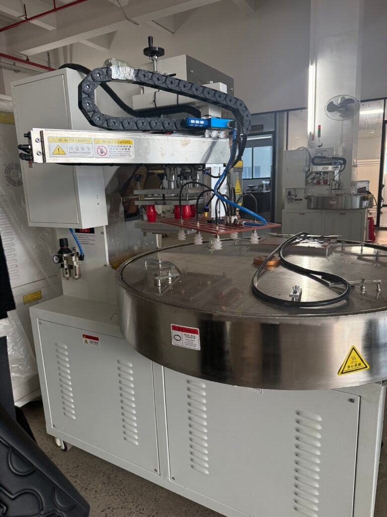
Water Cooling System
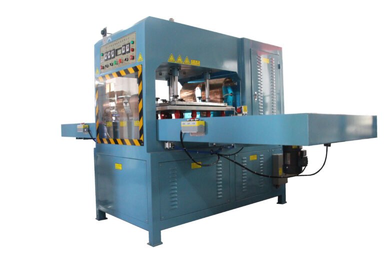
Many higher-power solid state HF welders still rely on water cooling for the IGBT heatsinks, the output matching network, and the press electrodes. The cooling system demands the same disciplined maintenance on a solid state machine as it does on a tube machine.
Monitor water quality with a conductivity meter every quarter. The coolant must remain clean and free of scale-forming minerals. Replace the coolant and flush the system on the same 12 to 18-month schedule used for the rest of the machine. Check all hoses for hardening, cracking, or signs of internal collapse. A restricted hose on a solid state machine still destroys the components it fails to cool.
Verify that flow switches and temperature sensors function correctly. A solid state generator’s self-protection circuits rely on these sensors to shut down the machine before thermal damage occurs. Test each sensor during the annual service by simulating a low-flow or high-temperature condition and confirming the machine responds as designed.
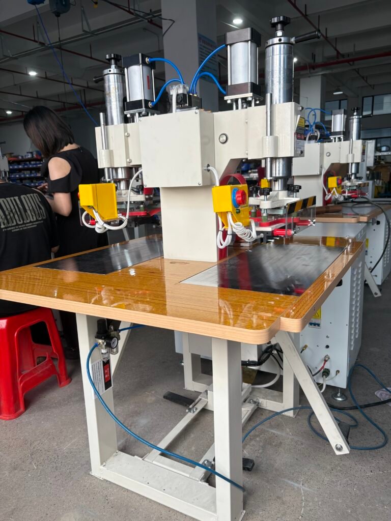
RF Output Stage and Matching Network
The RF output stage includes the combiner network, the output transformer, and the automatic tuning system if fitted. These components handle the full RF output power. Inspect them for any signs of arcing or overheating at the 12 to 18-month interval.
Check the automatic tuning capacitors and inductors for free movement. Lubricate actuator bearings according to the manufacturer’s specification. A sticking tuning element prevents the auto-tuner from maintaining the correct impedance match, which reduces power delivery and can cause the generator to shut down on a reflected power alarm.
Inspect the coaxial output cable and its connectors. Look for corrosion, loose center pins, or signs of water ingress. A damaged coaxial cable on a solid state generator reflects power back to the output stage, where the protection circuits may trip repeatedly. Replace any cable that shows physical damage or measures outside its specified impedance.
Control Electronics and Firmware
The PLC, HMI, and control boards in a solid state machine are generally reliable but still benefit from periodic attention. Back up all welding recipes and PLC programs at every service interval. Store the backup on a USB drive and a network location separate from the machine.
Check the internal battery that maintains the PLC memory and real-time clock. Replace it on the schedule recommended by the PLC manufacturer, typically every two to three years. A dead battery wipes all stored recipes and forces a complete reprogramming effort.
Inspect the inside of the control enclosure for dust accumulation. Blow out any dust with low-pressure, dry compressed air. Dust on control boards insulates heat and can cause intermittent faults. Check that all cable connectors inside the enclosure are fully seated. Thermal cycling can work connectors loose over time.
Recommended Service Interval: Why 12 to 18 Months Works
The question of how often service HF welding machine equipment depends on usage, but a 12 to 18-month interval works well for most solid state machines in normal production environments. This interval catches the slow degradation mechanisms before they cause failures without burdening the maintenance team with excessive downtime.
A machine running a single shift per day can extend the service interval to 18 months. The thermal cycling is less frequent, and the total operating hours per year are lower. A machine running three shifts per day should be serviced every 12 months, or even every 9 months if the duty cycle is very high.
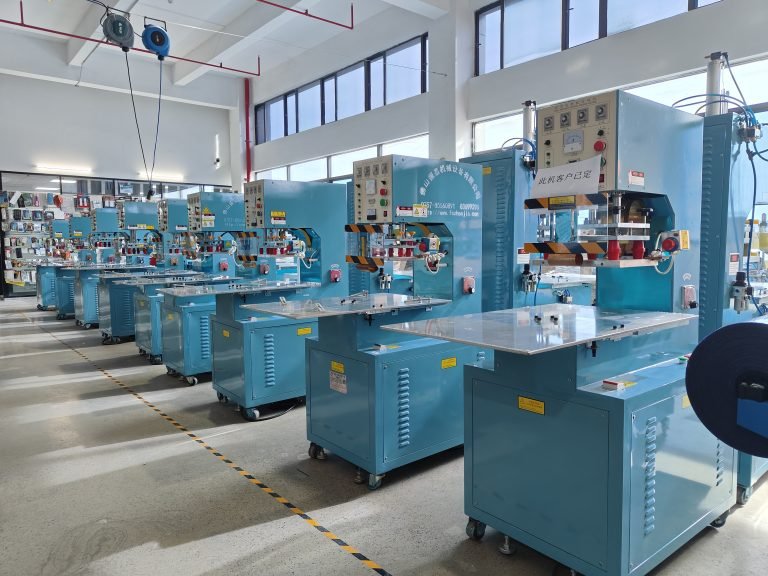
Stagger the service of multiple machines rather than taking them all offline simultaneously. Schedule the service during a planned production lull. Allocate a full day for a thorough solid state machine service. The actual hands-on time may be four to six hours, but allowing a full day provides time for unexpected findings, such as a capacitor that needs replacement and requires waiting for a spare part.
The True Cost Advantage of Solid State Maintenance
IGBT HF welder service costs less than tube machine service for reasons beyond the missing tube. The lower internal voltages mean less rigorous cleaning and insulation testing. The modular design of the power stages allows replacement of individual IGBT modules rather than a single expensive oscillator tube. The automatic tuning system eliminates the skilled manual tuning procedure required by many tube machines.
The biggest cost advantage, however, is the predictability. A tube machine may run perfectly for months and then fail suddenly when the tube arcs or loses vacuum. The emergency repair stops production, costs a premium for expedited parts, and may require a specialized technician. A solid state machine on a 12 to 18-month maintenance schedule very rarely fails without warning. The components that wear out are identified and replaced during scheduled service windows.
This predictability allows better production planning, lower spare parts inventory costs, and consistent product quality. The solid state welder maintenance cost advantage therefore extends beyond the service bay and into the production metrics that drive profitability.
Maintaining the Maintenance Schedule
A solid state RF welder upkeep program only works when it is followed. Set a recurring calendar reminder for the 12 or 18-month service date. Keep a service logbook that records every inspection, measurement, and replacement. Note the capacitance readings, the thermal compound condition, and the water quality test results. Trends in this data predict future needs.
Train at least one person in your organization to perform the solid state machine service procedures. Relying entirely on the equipment supplier for routine service introduces scheduling delays and higher costs. Reserve supplier service for major repairs, software updates, or complex diagnostics that exceed in-house capabilities.
A well-maintained solid state HF welding machine runs reliably for a decade or more. The few hours of scheduled maintenance invested each year return thousands of hours of trouble-free production. The machine that never breaks down during a critical order justifies its maintenance program many times over.