 TEL +86-13923172919
RF Welding Pinholes Seam and Weld Ripples: How to Diagnose and Correct HF Weld Quality Problems
A visually perfect HF weld communicates quality. Ripples, pinholes, and surface pits communicate the opposite. These surface defects weaken the seam, compromise airtight integrity, and increase scrap rates. Even worse, they erode customer confidence before the product ever reaches a functional test.
High frequency welding surface defects do not appear randomly. Each defect type leaves a distinct signature that points directly to its root cause. Ripples trace back to mechanical misalignment and incorrect V-angle geometry. Pinholes indicate overheating, contamination, or gas entrapment. Surface pits result from embedded debris, arc burns, or material flow problems.
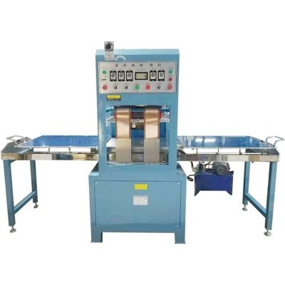
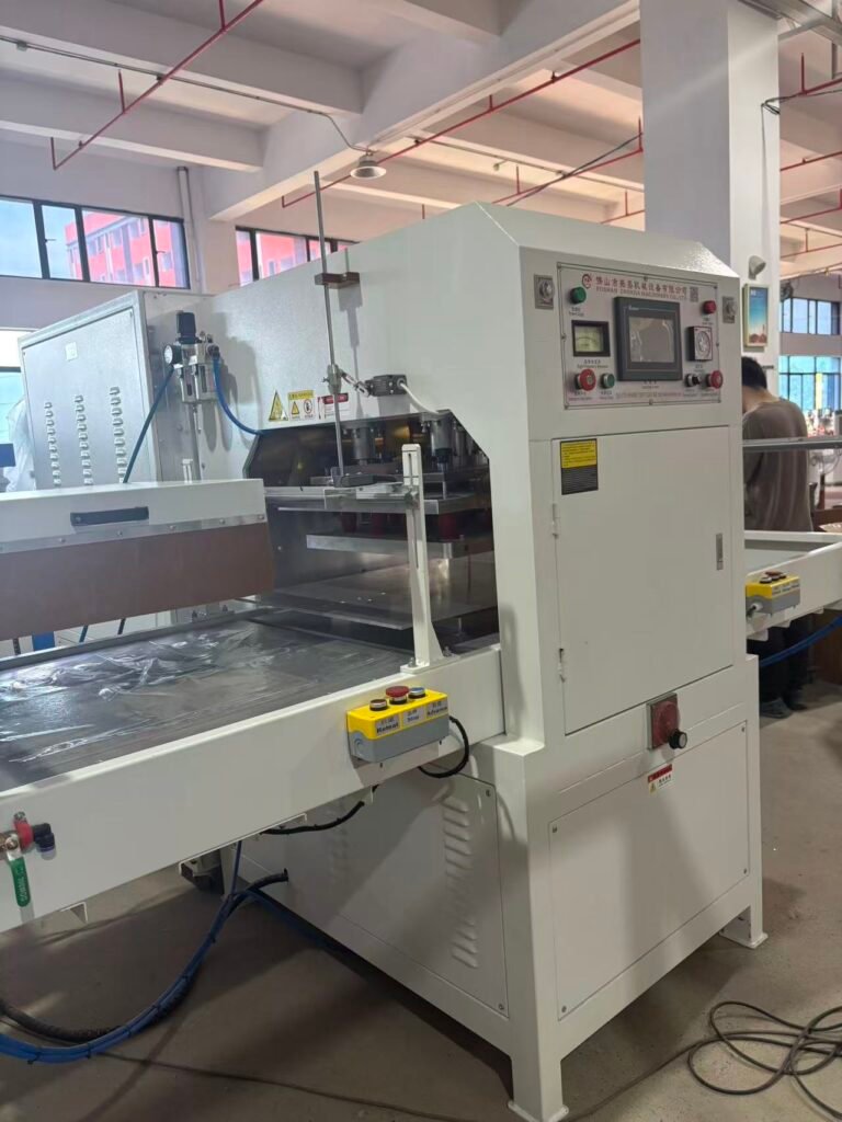
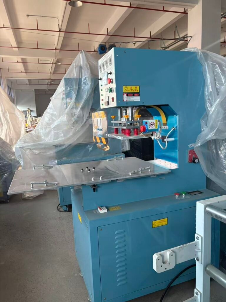
This guide examines each of these three common HF weld quality problems in detail. You will learn the specific cause behind each defect and the precise adjustment that eliminates it. We reference both HF Pipe Welding Machine configurations, where guide roll positioning is critical, and Push Plate HF Welding Machine setups, where die pressure and alignment dominate the equation.
Weld Ripples: The Signature of Mechanical Misalignment
HF welding weld ripples appear as regular, wave-like patterns running perpendicular to the weld direction. They feel like corrugation under a fingertip. These ripples indicate that the molten material is not flowing smoothly into the weld zone. Instead, it pulses or stutters as it solidifies.
Ripples rarely come from the RF generator. They almost always originate in the mechanical setup. Four primary causes account for the vast majority of ripple defects.
Incorrect V-Angle Opening
The V-angle is the gap between the two material edges as they approach the weld point. An angle that is too wide allows the edges to flutter before they meet. This flutter creates alternating zones of excess and insufficient material, which solidify into ripples. An angle that is too narrow starves the weld zone of material and generates similar instability.
How to fix it:
Measure the V-angle at the apex where the edges first contact. For most thermoplastic tube and sheet welding, this angle should sit between 4 and 7 degrees. Reduce the angle by moving the guide rolls closer to the weld point or by adjusting the forming fins. On a HF Pipe Welding Machine, this adjustment directly controls the edge presentation. Narrow the gap until the material enters the weld point smoothly without forcing. A stable V-shape with no visible edge vibration eliminates ripple formation at the source.
Misaligned Guide Rolls or Pressure Rolls
The guide rolls position the material precisely as it enters the weld zone. A single roll offset by half a millimeter causes one edge to ride higher than the other. The weld must then bridge a vertical mismatch, creating a ridge that manifests as a ripple pattern. Worn bearings in the guide rolls introduce periodic vibration that etches a matching ripple frequency directly into the cooling weld.
How to fix it:
Check all guide roll positions with a dial indicator relative to the weld centerline. Roll faces must sit parallel to the material surface and perpendicular to the machine centerline. Replace any roll with detectable bearing play. On a HF Pipe Welding Machine, verify that the squeeze rolls apply equal pressure from both sides and that their axes align perfectly with the tube centerline. Lock down all adjustment screws after positioning and recheck after the first production run.
Incorrect Squeeze Pressure or Timing
Insufficient squeeze pressure fails to consolidate the molten material into a homogeneous bead. The material solidifies before the edges fully knit, leaving a rippled surface. Excessive pressure squeezes out too much melt, creating a sunken center that looks like a continuous ripple.
How to fix it:
Adjust the squeeze pressure until the weld bead shows a slight, even crown on both the inside and outside surfaces. Start at the low end of the manufacturer’s recommended range and increase gradually. Observe the bead profile after each adjustment. The correct pressure produces a smooth, uninterrupted bead with no surface waves. This applies equally to a Push Plate HF Welding Machine, where the die pressure and parallelism determine bead formation.
Inconsistent Welding Speed or Power Fluctuation
If the line speed varies or the RF power oscillates, the heat input per millimeter of weld length fluctuates. This thermal pulsing expands and contracts the melt pool volume in a regular cycle, printing ripples into the surface. A worn drive motor, slipping puller belts, or a generator with poor regulation can all cause this.
How to fix it:
Verify that the line speed remains constant under load. Use a tachometer on the drive rollers. Service or replace any drive component that shows speed variation. On the generator side, check that the automatic power regulation circuit is engaged. A PLC controlled HF welder with closed-loop power control eliminates this cause entirely by maintaining constant output regardless of line voltage changes.
Pinholes: When Overheating and Contamination Create Tiny Leak Paths
RF welding pinholes seam defects appear as small, crater-like holes penetrating through the weld bead. In transparent materials, they show as tiny bubbles trapped in the weld line. A single pinhole can cause a medical bag to fail a leak test or an inflatable product to go flat overnight. Pinholes require immediate attention because each one represents a point of total barrier failure.
Overheating and Material Degradation
The most common cause of pinholes is excessive RF energy that pushes the material temperature beyond its degradation point. The polymer decomposes, releasing gas bubbles that burst through the molten surface and leave pinholes. This is classic over-welding. The seam may look strong, but the pinholes make it functionally useless.
How to fix it:
Reduce the RF power setting or shorten the weld time. Aim for the minimum energy that produces a fully fused seam. Perform a tear-down test: a properly welded seam tears through the parent material, not along the bond line. A seam that separates with a brittle fracture or shows discoloration has received too much power. Back off the setting by 10% increments until the pinholes disappear and the tear test still passes. This HF weld quality problem solves quickly once the energy input matches the material’s true thermal tolerance.
Moisture and Volatile Contaminants
Water absorbed by hygroscopic materials like nylon, PET, or even stored PVC flashes into steam at welding temperature. The steam bubble expands violently, breaches the melt surface, and leaves a pinhole behind. Residual solvents, oils, or plasticizer migration create the same effect.
How to fix it:
Store material in a dry, temperature-controlled environment before welding. Pre-dry hygroscopic materials according to the supplier’s specifications, typically 2 to 4 hours at 60°C to 80°C. Clean all material surfaces with isopropyl alcohol and a lint-free wipe immediately before loading into the machine. This step proves especially critical on a Push Plate HF Welding Machine welding multi-layer medical pouches, where any trapped contamination generates pinholes that fail ISO 11607 seal integrity requirements.
Dirty or Arcing Electrodes
A contaminated die surface creates localized hot spots. Contamination concentrates the RF field at the contaminant edges, vaporizing both the contaminant and surrounding polymer. The resulting arc pit may penetrate entirely through the material as a pinhole. The weld pit HF welding machine connection is direct: a pitted die face stamps surface defects into every subsequent part.
How to fix it:
Clean the electrode sealing faces on a fixed schedule. Use a fine brass brush or non-woven abrasive pad to remove built-up residue. Wipe down with isopropyl alcohol. If pitting is already present, resurface or replace the die. Running a damaged die destroys product and wastes production time. Implement arc detection on the generator to halt the cycle at the first spark, preventing cascade damage to the die surface.
Insufficient Weld Pressure
Low pressure allows gas bubbles to nucleate and grow within the melt. The bubble stays trapped because the surrounding material never compresses it into solution. When the material solidifies, the bubble cavity remains as a pinhole.
How to fix it:
Increase the press pressure until the molten material squeezes bubbles out of the weld zone. A slight bead of flash material on each side of the seal indicates adequate consolidation pressure. Monitor the flash appearance: a smooth, continuous flash suggests effective bubble evacuation. A discontinuous or foamy flash points to trapped gas.
Surface Pits: From Embedded Debris to Arc Burns
Surface pits appear as small, irregular depressions that do not fully penetrate the material. They mar the appearance of the product and act as stress concentrators that can initiate tears under load. Pits form through several distinct mechanisms, each requiring a different countermeasure.
Embedded Foreign Particles
A dust particle, a strand of fiber, or a tiny piece of trimmed flash can land on the material surface before welding. The RF energy heats the particle faster than the surrounding polymer. The particle chars, shrinks, or bonds only weakly to the matrix, falling out later and leaving a pit. This high frequency welding surface defects cause is common in factories where trimming and welding occur in the same area.
How to fix it:
Establish a clean-zone protocol around the welding station. Use ionized air blowers to neutralize static that attracts dust. Install brushes or tacky rollers on the material infeed path to capture loose particles before they reach the die. On a HF Pipe Welding Machine, protect the incoming strip from airborne debris with covers over the feed path. A clean operation eliminates random pitting events.
Arc Burns and Micro-Arcing
Even a tiny arc event etches a pit into the material surface. Unlike through-pinholes, these arcs are small enough that the surrounding melt partially refills the crater. The result is a shallow depression with a discolored, carbonized base. Micro-arcing often occurs at the edges of the sealing die where the electric field concentrates.
How to fix it:
Break all sharp edges on the die profile. Add a small radius to the sealing edge corners. Verify that the die face sits perfectly parallel to the counter electrode. Install or tune the arc suppression circuit to cut power at the first indication of a discharge. Every arc that fires digs a pit. Preventing arcs is the only durable solution.
Material Inhomogeneity
Some PVC compounds contain poorly dispersed filler, pigment agglomerates, or gelled particles. These inhomogeneities absorb RF energy at a different rate than the surrounding polymer. The particle overheats, degrades, and leaves a pit. Batch-to-batch material variation often produces sudden outbreaks of pitting on a previously stable process.
How to fix it:
Test incoming material batches with a small production run before committing to full-scale manufacturing. If pitting appears on a new batch but the machine parameters remain unchanged, suspect the material. Work with your compound supplier to improve dispersion quality. For in-house compounding, increase mixing time or shear to break down agglomerates.
Incorrect Cooling Under Pressure
If the press opens before the material solidifies completely, the still-soft surface collapses slightly as it cools in free air. This creates shallow, broad depressions rather than sharp pits. The defect pattern repeats consistently with the cycle timing.
How to fix it:
Extend the cooling time within the press cycle. The material must drop below its softening point before the die retracts. On a Push Plate HF Welding Machine, the cooling time is a standard PLC parameter. Increase it in 0.5-second increments until the pits disappear. Verify that cooling water flows adequately through the electrodes. Insufficient die cooling extends the required dwell time and can cause thermal buildup that shifts the process out of its window over a production run.
Integrated Quality Control for Defect-Free HF Welds
Preventing HF weld quality problems requires a systematic approach. Install a magnifying inspection lamp or machine vision camera at the weld station exit. Train operators to recognize each defect type and log it immediately. Correlate defect appearances with machine parameter changes, material batch numbers, and maintenance events.
Document the optimal V-angle, power setting, pressure, and cooling time for each product in a machine recipe. When defects appear, compare current parameters against the stored recipe. Many times a parameter has drifted or an operator has over-adjusted. Returning to the known-good baseline resolves the issue without guesswork.
Schedule die cleaning and guide roll inspection at fixed cycle-count intervals. The machine itself cannot clean its own tooling. Preventive maintenance on the mechanical components that position and compress the material prevents the misalignments that cause ripples and pits.
Restoring Surface Perfection One Parameter at a Time
Every ripple, pinhole, and pit has an addressable cause. Weld ripples point to the mechanical setup. Adjust the V-angle, align the guide rolls, stabilize the speed, and the surface smooths out. Pinholes point to excess energy or contamination. Reduce power, dry the material, clean the die, and the leaks stop. Surface pits point to debris, arcs, or material quality. Clean the environment, suppress arcs, vet the compound, and the finish cleans up.
A HF welding machine produces the energy, but precision in the mechanical setup and cleanliness in the process deliver the surface quality. When your seam looks flawless, your product communicates quality before the customer even tests it. Methodical defect analysis keeps it that way.