How to Weld Rigid PVC to Soft PVC Film on an HF Welding Machine Without Burning: A Complete Process Guide
Soft PVC film welds easily. Rigid PVC fittings also weld easily. The challenge appears when you try to weld them to each other in the same joint. The soft film reaches welding temperature and starts to melt while the rigid fitting remains cold and solid. The operator increases power or time to melt the rigid part. The soft film scorches, discolors, or burns through entirely. Welding rigid PVC to soft PVC HF demands a fundamentally different approach from welding a single material.
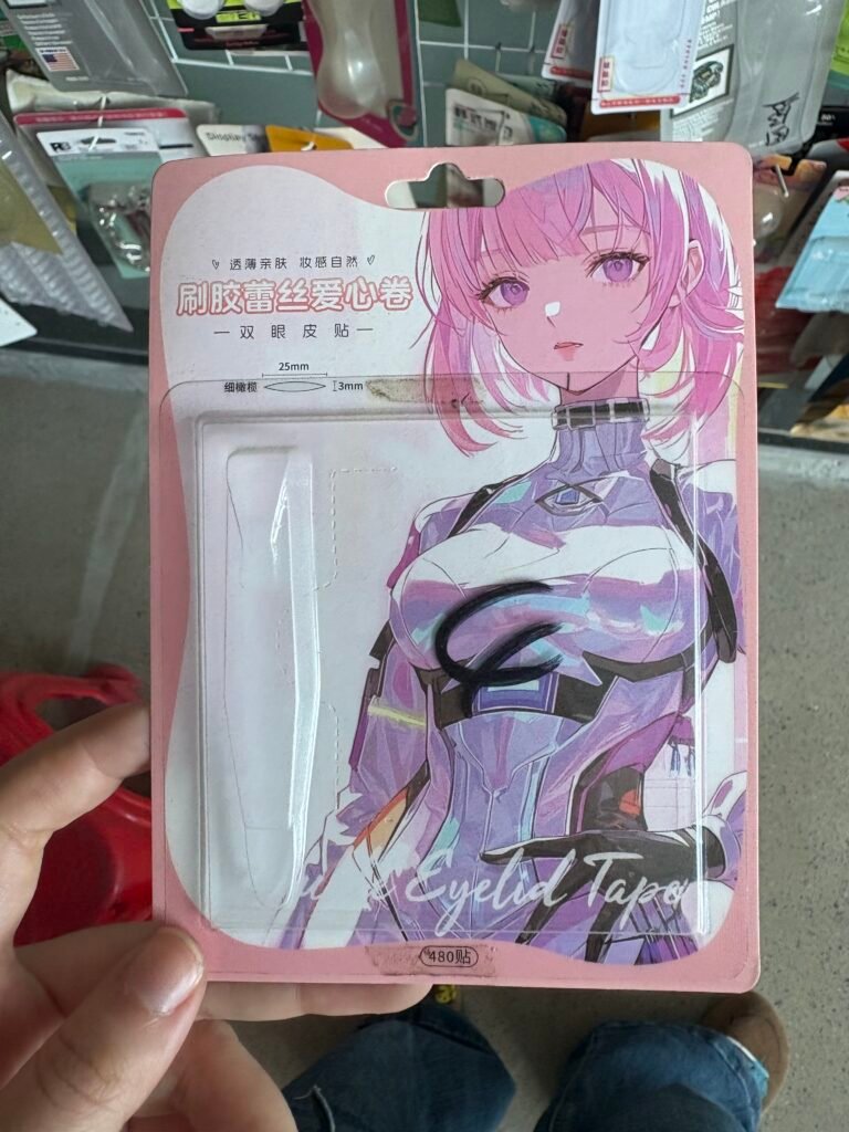
This problem surfaces most often in medical device manufacturing. A soft PVC bag film must bond to a rigid PVC port or connector. The joint must seal completely, pass pull tests, and survive sterilization without leaking. Traditional single-material welding recipes fail on this assembly every time.
A successful RF welding mixed PVC thickness process accounts for the differing thermal responses of rigid and soft PVC. It manages heat flow so both materials reach their processing temperature simultaneously. It supports the rigid part mechanically so it does not shift under pressure. This guide explains how to achieve that balance.
Understanding the Physical Difference Between Rigid and Soft PVC
Both materials are polyvinyl chloride. The difference lies in plasticizer content. Soft PVC contains a significant percentage of plasticizer, typically 30% to 50% by weight. The plasticizer molecules separate the polymer chains and lower the glass transition temperature. Soft PVC becomes flexible at room temperature and melts at 120°C to 150°C under RF energy.
Rigid PVC contains little or no plasticizer. The polymer chains pack tightly together. The glass transition temperature sits around 80°C. The material requires 160°C to 200°C to soften enough for welding. This temperature gap of 30°C to 80°C between the melting points of soft and rigid PVC explains why burning happens.
RF energy heats both materials simultaneously. The soft film reaches its melting point first. While it sits molten, waiting for the rigid part to catch up, it degrades. The plasticizer begins to decompose. The polymer chains break. Discoloration, bubbling, and charring follow. The HF welding PVC connector to film process must close this timing gap to produce a sound joint.
The Role of Buffer Material and Thermal Balancing
A buffer material inserted between the electrode and the soft PVC film slows the heating rate on the film side. This gives the rigid PVC time to heat through before the soft film overheats.
Silicone rubber and Teflon sheet both serve as effective thermal buffers. A 0.5mm to 1.0mm layer placed directly between the upper electrode and the soft film reduces the energy transfer rate into the film. The buffer absorbs some RF energy and converts it to heat within itself rather than passing it straight into the soft PVC. The soft film heats more slowly and more evenly.
The rigid PVC side receives direct electrode contact. No buffer impedes energy flow into the fitting. The rigid material heats at its maximum rate. The asymmetric heating arrangement compensates for the different melting points. Both sides of the joint reach their respective processing temperatures at approximately the same moment.
Selecting the correct buffer thickness requires a few test runs. Start with a 0.5mm silicone sheet. Make a weld and perform a pull test. If the soft film still shows scorching, increase the buffer thickness to 0.8mm or 1.0mm. If the rigid PVC does not fully fuse, reduce the buffer thickness or increase the cycle time slightly. The goal is a clean, unburned soft film bonded to a fully softened rigid fitting.
Support Tooling: Holding the Rigid Part in Place Under Pressure
A rigid PVC fitting does not collapse like a soft film under press pressure. It resists. This resistance creates a mechanical problem. The press applies tonnage across the entire die area. The soft film compresses easily. The rigid fitting does not. The pressure concentrates at the rigid part. The film areas surrounding the fitting receive insufficient pressure and produce weak or incomplete seals.
A support fixture solves this distribution problem. The fixture, often machined from aluminum or phenolic, surrounds the rigid fitting and fills the empty space within the die area. Its height matches the compressed height of the fitting. When the press closes, the fixture absorbs pressure in the open areas. The rigid fitting absorbs pressure at the joint. The soft film experiences uniform compression everywhere.
The fixture also locks the fitting in position. A connector that shifts during the press stroke produces a misaligned seal. The fixture holds it precisely in the correct orientation. For high-volume medical production, the fixture integrates into the die set as a spring-loaded or pneumatically actuated nest. The operator places the fitting into the nest, drapes the film over it, and initiates the cycle. The fixture does the rest.
Power and Time Parameter Selection for Mixed PVC Welding
Standard parameter rules still apply, but the starting point shifts. The RF welding mixed PVC thickness process uses lower power and longer time than same-material welding. The extended time allows heat to conduct from the soft film into the rigid fitting. The lower power prevents the soft film from scorching during that extended exposure.
Begin with a power setting at 60% of what you would use for welding two layers of the same soft PVC film. Set the weld time to approximately 150% of the normal duration. Perform a test weld. Examine the soft film for any sign of browning or transparency loss. Cut the weld and inspect the cross-section for complete fusion of the rigid PVC surface.
If the rigid PVC shows incomplete surface melting, increase the time in 0.5-second increments. Do not increase the power. Extra time conducts heat into the rigid part. Extra power dumps more energy into the already-hot soft film and causes burning. The correct parameter set achieves full fusion of both materials with zero discoloration.
A high frequency welding PVC fittings recipe for a typical medical bag port might use 6kW to 8kW of power over 4 to 6 seconds, compared to 10kW over 2 seconds for the same thickness of soft film alone. Every tooling setup and material combination requires its own optimized parameters. Document the proven recipe and store it in the machine PLC.
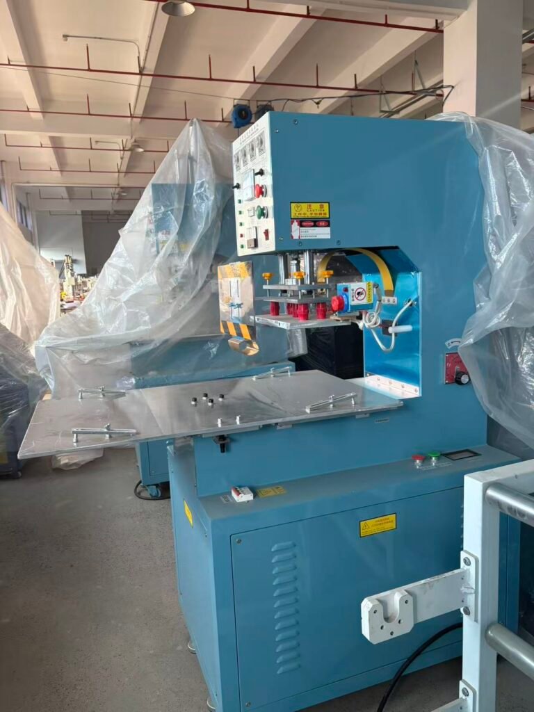
Using a Shuttle or Medical HF Welding Machine for Mixed PVC Assemblies
A standard push-plate machine can weld mixed PVC joints for low-volume production. The operator manually positions the fitting, the fixture, and the film for each cycle. At production volumes above a few hundred units per day, the manual handling time becomes the limiting factor.
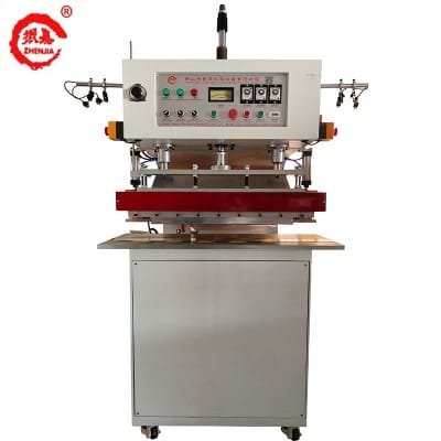
A Shuttle HF Welding Machine configuration addresses this. One table holds the fixture and material while the operator loads it outside the weld zone. The table shuttles into the press, the cycle runs, and the table returns. The operator unloads the finished assembly and loads fresh components without waiting for the weld cycle. This overlapping workflow doubles or triples output compared to a single-station manual setup.
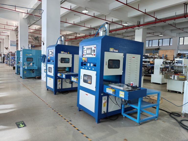
Medical device manufacturers often specify a Medical HF Welding Machine for these applications. These machines include features specifically required for regulated cleanroom production. Stainless steel frames resist cleaning chemicals. Sealed electrical enclosures prevent particulate shedding. PLC data logging captures every cycle parameter for batch traceability. The auto-tuning feature discussed in earlier chapters maintains consistent power delivery as the tooling heats up during a production run.
Testing and Validating Mixed PVC Welds
The joint between rigid and soft PVC must pass specific tests that a single-material weld might not face. Perform a tensile pull test on the rigid fitting. Clamp the soft film in one jaw and the fitting in the other. Pull at a controlled rate and record the force at failure. The failure mode matters as much as the force. A proper weld tears the soft film, not separates at the interface. Separation at the interface indicates incomplete fusion.
Conduct a leak test on the completed assembly. Pressurize the bag or tube assembly to its rated pressure plus a safety factor. Submerge it in water or use a pressure decay tester. No bubbles and no measurable pressure drop are acceptable. Repeat the test after sterilization cycling. Ethylene oxide and gamma irradiation both stress the weld interface. A joint that passes testing fresh out of the welder must also pass after the full sterilization regimen.
Section a sample weld and inspect the cross-section under magnification. The interface between the rigid and soft PVC should appear as a continuous, void-free transition zone. Gaps, voids, or a visible demarcation line indicate incomplete fusion or trapped air. Adjust the buffer thickness or cycle time until the cross-section shows full material integration.
Summary of Best Practices
Welding rigid PVC fittings to soft PVC film succeeds when the process accounts for the material asymmetry. Use a thermal buffer on the soft film side to slow its heating. Use a rigid support fixture to equalize pressure distribution and lock the fitting in position. Apply lower power for a longer time compared to same-material welding. Validate the joint with tensile, leak, and cross-section testing.
The welding rigid PVC to soft PVC HF challenge intimidates operators who have only welded uniform materials. A systematic approach turns it into a repeatable, validated process. Medical device manufacturers rely on this technique daily to produce safe, reliable fluid handling assemblies. With the right buffer, fixture, and parameters, your machine delivers the same result.