High Frequency Welding Machine EMC: How to Test and Control RF Welding Electromagnetic Leakage for CE and FCC Compliance
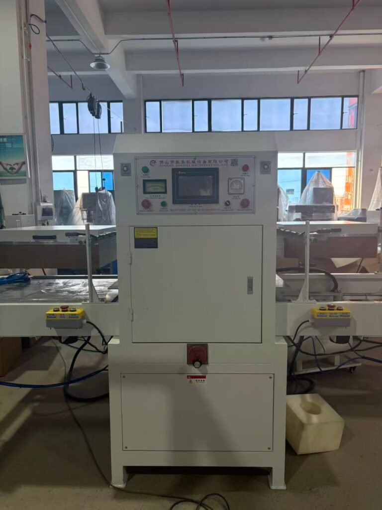
A high frequency welding machine generates powerful electromagnetic fields at its operating frequency. Properly contained, those fields stay inside the press and tooling. Improperly shielded, they radiate into the surrounding workspace. RF welding electromagnetic leakage creates two problems that demand immediate attention. It exposes operators to non‑ionizing radiation that can cause RF burns and thermal effects. It also disrupts sensitive electronics, violates radio communication regulations, and fails the high frequency welding machine EMC requirements mandated by international standards.
Meeting HF welder radiation safety standards is not optional for manufacturers exporting to global markets. European buyers require CE certification HF welding machine compliance. North American customers demand HF welding FCC compliance. Both regimes require documented proof that electromagnetic emissions stay below legally prescribed limits. This article explains where leakage originates, how frequency stabilizers and leakage suppressors contain it, and which test methods prove your machine operates safely within the emission boundaries.
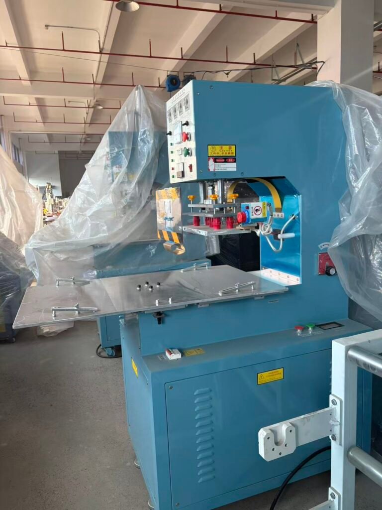
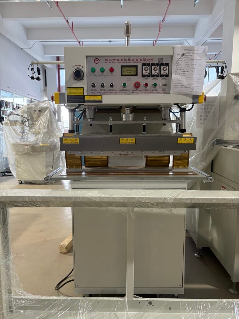
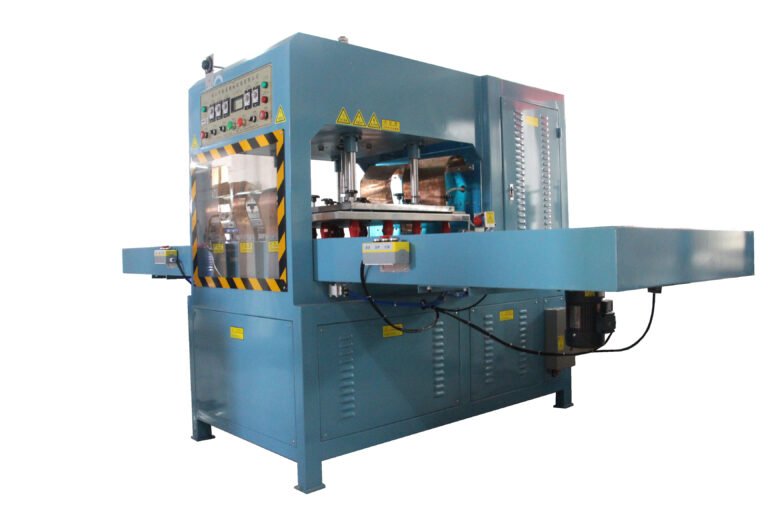
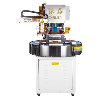
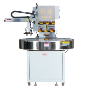
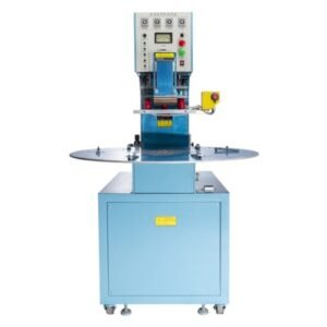
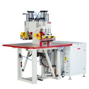
related products
Where Electromagnetic Leakage Originates in an HF Welder
Every component carrying RF current acts as a potential antenna. The electrode and its feed structure form the primary radiator. Gaps in shielding, unshielded coaxial cables, and poorly bonded enclosure panels all provide escape paths for electromagnetic energy.
Press electrodes behave like dipole antennas when they lack proper guarding. The upper and lower platens couple RF energy into the air between them. Operators standing near an unguarded press absorb some of that radiated energy. Even at levels below thermal perception, this exposure must stay within occupational limits defined by ICNIRP and national authorities.
Cable connections present another common leakage source. A coaxial cable with a loose connector shield or a pinched dielectric radiates RF along its entire length. Nearby metallic structures pick up this radiation and re‑radiate it unpredictably. Control cables entering the RF enclosure without proper filtering also carry conducted emissions out of the shielded compartment.
Enclosure seams and ventilation openings complete the list. An HF welding cabinet with a missing screw, a bent door, or an unfiltered cooling slot leaks electromagnetic energy. The leak may measure only a few watts, but those watts can exceed regulatory limits when measured at the prescribed distance.
How Frequency Stabilizers and Leakage Suppressors Contain RF Energy
Controlling electromagnetic emissions starts at the source. A frequency stabilizer locks the generator output to the assigned ISM frequency, typically 27.12 MHz or 13.56 MHz. Stabilization prevents the oscillator from drifting into adjacent frequency bands used by communication services. Drift produces out‑of‑band emissions that regulatory bodies treat far more strictly than in‑band emissions. A high frequency welding machine EMC design always includes a quartz‑referenced frequency source or a phase‑locked loop to maintain exact frequency control.
Leakage suppressors work on the principle of containment. Ferrite cores clamped around input and output cables act as common‑mode chokes. They present a high impedance to RF currents trying to flow on cable shields and a low impedance to the intended 50‑60 Hz power. Installing ferrite suppressors on all cables entering the RF enclosure reduces conducted emissions by orders of magnitude.
Shielding completes the containment strategy. Conductive gaskets around enclosure doors and panels maintain electrical continuity across removable joints. Mesh‑covered ventilation windows allow cooling airflow while blocking RF escape. Double‑shielded coaxial cable with continuous outer braid coverage prevents radiation from the feed line. Together, suppressors and shielding form a Faraday‑cage barrier that keeps RF energy inside the machine.
CE and FCC Requirements for High Frequency Welding Machines
Regulatory compliance for CE certification HF welding machine compliance follows the European EMC Directive 2014/30/EU. The applicable product standard is EN 55011, which classifies HF welders as Group 2, Class A equipment. Group 2 covers equipment that intentionally generates RF energy for material processing. Class A limits apply to industrial environments. The standard sets radiated emission limits of 30 dBµV/m to 42 dBµV/m at 10 meters for frequencies below 30 MHz, depending on the band. Conducted emission limits on the mains port also apply.
HF welding FCC compliance follows FCC Part 18 for industrial, scientific, and medical equipment. Like EN 55011, it classifies HF welders as ISM equipment operating in designated frequency bands. The FCC sets field strength limits at specified distances from the equipment. Users must not cause harmful interference to licensed radio services. If a machine does cause interference, the operator must cease operation and resolve the problem.
Both regulatory schemes require the manufacturer or importer to demonstrate compliance through testing. Self‑declaration is permitted for Class A equipment under EN 55011, but many customers demand third‑party test reports as a condition of purchase. The FCC requires a compliance information statement and equipment labeling. Non‑compliance carries penalties including fines, product recalls, and denial of market access.
Practical EMC Testing Methods for Your HF Welding Machine
Conducting an high frequency welding machine EMC pre‑compliance test in‑house catches emission problems before formal certification. A basic setup requires a spectrum analyzer, a calibrated near‑field probe set, and a biconical or loop antenna for radiated field measurements.
Start with conducted emission testing on the mains input. Insert a line impedance stabilization network (LISN) between the machine and the wall supply. Connect the spectrum analyzer to the LISN RF port and sweep from 150 kHz to 30 MHz. Compare the measured levels against the EN 55011 Class A conducted limits. Elevated readings indicate insufficient power line filtering.
Move to radiated emission testing. Position the receiving antenna at 3 meters or 10 meters from the machine, depending on the standard you target. Orient the machine and the antenna in both horizontal and vertical polarization. Record the maximum field strength at the operating frequency and at harmonics. Use the spectrum analyzer in max‑hold mode while the machine cycles through complete weld sequences under normal load.
Near‑field probing locates specific leak sources. Walk a magnetic field probe along cabinet seams, around cable entries, and near the electrode assembly. Watch the spectrum analyzer trace for amplitude peaks that identify gaps in shielding. Mark each leak point and apply conductive gasketing, ferrite clamps, or mesh screening as needed. Re‑test after each fix to verify improvement.
For HF welder radiation safety, measure the electric field strength at operator positions. Wearable RF exposure monitors or isotropic field probes provide the most relevant data. Compare the readings to the occupational exposure limits published by ICNIRP. If levels approach the limit, add operator shielding, increase the distance between the operator and the press, or reduce the duty cycle of RF exposure.
Building Compliance into Your Machine from the Start
Retrofitting EMC controls onto an existing machine costs more than integrating them into a new build. When specifying a high frequency welding machine EMC package, confirm that the manufacturer includes a frequency‑stabilized generator, an output matching network with harmonic filtering, shielded coaxial cables, and a fully gasketed enclosure. Request a copy of the EC Declaration of Conformity or FCC test report before shipment. Verify that the documentation covers your exact model and configuration.
Regular inspection maintains compliance over the machine’s life. Check enclosure gaskets for compression set and damage during routine maintenance. Verify that cable shields remain intact and connector shells are tight. Re‑test emissions after any modification that changes the RF path, including die changes that alter the load impedance.
A high frequency welding machine leaking electromagnetic radiation is not just a regulatory liability. It is a signal of deficient shielding that compromises both safety and process stability. Contain the fields, test the emissions, and document the results. The quiet electromagnetic signature of a compliant machine reflects the engineering discipline that also produces consistent, high‑strength welds.