 TEL +86-13923172919
How to Set Up High Frequency Welding Machine for First-Time Use: Parameters, Safety Checks, and Test Welds
A small plastics factory in Malaysia just received its first high-frequency welding machine. The production manager has 20 years of experience in injection molding but has never touched an RF welder. The machine sits on the shop floor—crated, untouched, and intimidating. Where does he start? Which switch flips first? What happens if he gets the settings wrong?
This scenario plays out every day across Southeast Asia’s manufacturing sector. A high-frequency welding machine is not a plug‑and‑play appliance. Improper setup leads to poor weld quality, damaged molds, shortened tube life, and—in the worst case—electrical shock or fire.
This guide walks through the complete first‑time setup process for a high‑frequency welding machine, covering electrical connection, grounding verification, power warm‑up, test welding, and parameter fine‑tuning. Whether you are setting up a push‑plate type machine for PVC tarpaulin or a standard press for automotive interior parts, the principles remain the same.
Step 1: Unpacking and Site Preparation
Do not power on immediately after receiving the unit. Complete the following checks first:
- Unpack and inspect the machine surface and all components for shipping damage.
- Check that all screws are tight, electrical connectors are locked, and accessories are complete.
- Place the machine on a level, rigid floor, at least 0.5 m away from heat sources, with at least 1 m of operating space in front.
- Confirm ambient temperature is between 5 °C and 35 °C, relative humidity ≤75 %, and no condensation.
- Lay insulating rubber mats of at least 3 mm thickness on the floor around the operator position.
For push‑plate type machines, installation is simpler: the die is mounted on the push‑plate board – just fix it in place and ensure the upper and lower dies are parallel and free of debris. Always disconnect power before installing or adjusting dies.
Step 2: Electrical Connection and Voltage Verification
Electrical connection is the most critical step in first‑time setup. Incorrect wiring can damage the machine or cause safety hazards.
- Check the voltage rating – read the label on the oscillator cabinet and match it to your site supply. Different models have different requirements (e.g., AC220V, 50‑60 Hz).
- Connect the power cable to a properly rated supply. Turn on the main three‑phase supply, then turn on the power switch on the side control panel.
- Verify motor rotation direction – after energising, check that the motor turns in the direction shown by the arrow on the motor label. If reversed, swap any two phase wires at the terminal block.
- Do not turn on the high‑frequency (RF) switch yet. Turn on the electric heating power first – this starts preheating the vacuum tube and the hot die.
Important: Confirm that all power cables, sockets, and fuses are tightly connected. Grounding resistance must be ≤4 Ω.
Step 3: Grounding Verification – The Most Important Safety Step
A high‑frequency welder generates strong electromagnetic fields. Poor grounding not only interferes with nearby electronics but also exposes operators to radiation risks. Proper grounding is mandatory.
- Use a ground rod driven into moist soil, as close to the machine as possible – ideally within 3 m (10 ft) of the grounding connection point.
- Alternatively, a cold water pipe that enters the ground within 10 ft of the machine may be used.
- Keep the ground wire as short as possible, and use a cable of the same or larger gauge than the working cable.
- Do not connect the ground back to the circuit ground – this can create harmful high‑frequency feedback.
- Avoid grounding to building steel, electrical conduits, or long pipe runs – they can re‑radiate and become antennas.
For older models, consider installing a “ground mat” device to reduce operator EMF exposure.
Step 4: Air Supply and Cooling System Check
High‑frequency welders typically require compressed air and cooling:
- Air supply: connect to a clean, oil‑free compressed air source with rated pressure generally at 0.6 MPa. Confirm supply pressure is 3–6 kg/cm².
- Water cooling: start the water cooling system and check that water pressure is 0.2–0.3 MPa and water temperature is below 35 °C. Inspect the cooling tank, pipes, and pump for proper operation. Confirm all water connections are tight with no leaks and the water level is sufficient.
- Air cooling: check that the fan inside the high‑frequency controller runs smoothly and without abnormal noise.
Step 5: Warm‑Up – The 10‑15 Minutes You Must Not Skip
Never skip the warm‑up before turning on the RF switch. Cold starts cause arcing and shorten tube life.
- After turning on the electric heating power, the vacuum tube and hot die begin preheating.
- Warm‑up time should be 10‑15 minutes.
- Benefits of warm‑up: raises internal RF tube power, maintains good vacuum state, stabilises high‑frequency output, and extends tube service life.
Use this time to complete die mounting and adjustments.
Step 6: Die Mounting and Leveling Adjustment
During warm‑up, mount and adjust the dies:
- Lay insulating material on the lower die, and install the upper die on the upper platen.
- Press the trial‑mode switch and start adjusting the upper‑lower die alignment.
- If the lower die is misaligned, move its position.
- If the level is off, adjust the four supporting screws on the upper platen.
- In manual mode, slowly close the dies and adjust the leveling screws until the gap around the dies is uniform and the clamping force is balanced.
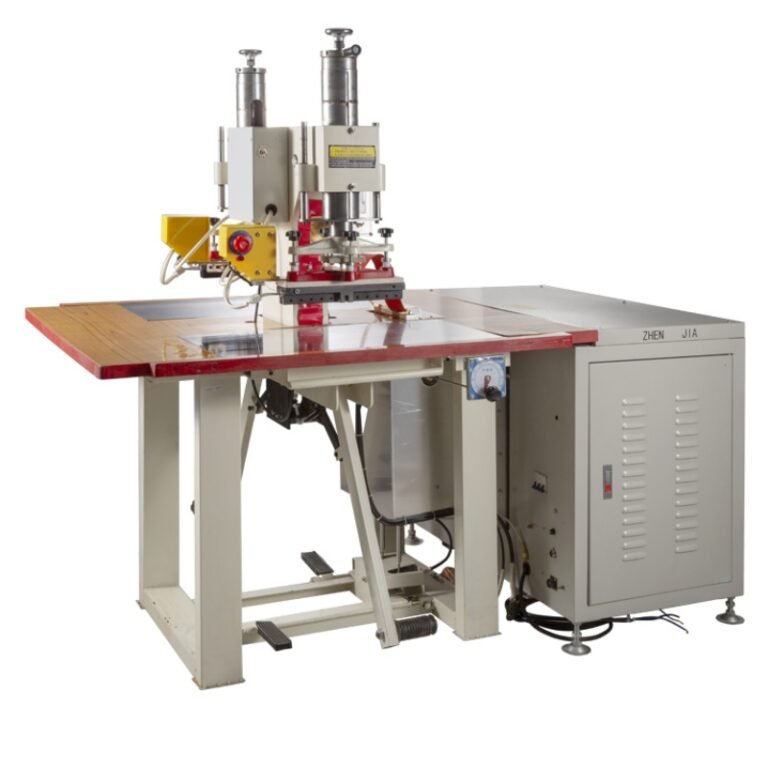
For push‑plate type: the die is mounted on the push‑plate board. The operator pushes the left and right slides alternately under the head for welding – this dual‑station design allows synchronous operation.
Step 7: Timer Settings
Most high‑frequency welders have three timers:
| Timer | Function | First‑time suggestion |
|---|---|---|
| Descend time | Time for upper die to travel down and press the material | Adjust according to die stroke |
| Weld time | High‑frequency output duration | Start short – e.g., 0.5‑3 seconds |
| Cool time | Holding/curing time under pressure | 1‑3 seconds |
For foot‑operated models, usually only the weld timer is present.
Principle: too short a weld time reduces bond strength; too long burns or punctures the material. Always start with short times and increase incrementally.
Step 8: Tuning Adjuster (Oscillator Matching) – The Most Critical First‑Time Step
For first‑time die tuning, set the tuning spacing to the widest position. This prevents excessive inrush current from damaging the tube or die.
Only after completing warm‑up (10‑15 minutes) and reaching temperature, turn the RF switch ON and proceed to test welding.
Step 9: Function Test Without High Frequency (Dry Run)
Before enabling RF power, perform a dry run:
- Turn Power SW ON. Set manual/auto selector to “Manual” and RF switch to “OFF”.
- Press the “Manual Up” red button (die rises) and place the welding material.
- Press the “Manual Down” green button (head descends) to clamp the material.
- If the die does not clamp evenly, adjust the leveling screws.
- Set the timers (recommended starting values: e.g., 2s descend – 2s weld – 2s cool, or according to your actual material).
Only after confirming all mechanical actions are normal, proceed with the RF‑enabled test.
Step 10: Test Welding With High Frequency Enabled
- Set the RF switch to “ON”.
- Press the yellow “RF Start” button to begin the test weld.
- Slowly rotate the RF adjustment knob clockwise with your left hand while watching the RF ammeter.
- Ensure the RF ammeter pointer rises slowly from zero.
- Observe the weld quality.
Current reference (varies by model – always refer to your manual): for 2‑layer material, the pointer may reach 7‑9 scale; for 4‑layer material, 12‑14 scale.
Step 11: Parameter Fine‑Tuning – The Decisive Factor for Finished Product Quality
Final weld quality depends on four interrelated parameters:
- Temperature – keep the hot die at a moderate temperature to assist setting. Too hot causes sticking; too cool reduces setting.
- Tuning output – start from low power and increase slowly while watching the ammeter.
- Pressure – set so that the material is not crushed but the weld surfaces are tightly joined. Insufficient pressure causes weak bonds; excessive pressure deforms the workpiece.
- Weld time – adjust based on material thickness and type.
Fine‑tuning principle: if the test weld is unsatisfactory, increase or decrease the tuning gradually while watching the plate current. Check the product and adjust the tuning slightly up or down until you achieve a clean, strong weld. Follow the core rule: Safety first, then leveling, then parameters, and always start small and increase gradually.
Critical Safety Warnings for First‑Time Setup
- Only personnel who have received proper machine operation and industrial safety training may operate the equipment.
- Always inspect power, grounding, cooling, and all connections before starting.
- Operators must wear insulating gloves, safety glasses, and protective clothing.
- Keep at least 1 m distance from the high‑frequency generator unless necessary.
- Never energise the machine with the cabinet door open – the door must have an electrical interlock.
- Never operate if input voltage is too high.
- Never run the machine with abnormal cooling.
- Remember: the RF output of a high‑frequency welder is similar to a radio transmitter – treat it with respect.
First‑Time Setup Quick Checklist
| Check Item | Status |
|---|---|
| Machine surface and components free of shipping damage | ☐ |
| All screws tightened, electrical connectors locked | ☐ |
| Machine level and ≥0.5 m from heat sources | ☐ |
| Ambient temp 5–35 °C, humidity ≤75 % | ☐ |
| Grounding resistance ≤4 Ω, ground wire as short as possible | ☐ |
| Air supply pressure 3‑6 kg/cm² (0.6 MPa) | ☐ |
| Cooling water pressure 0.2‑0.3 MPa, water temp <35 °C | ☐ |
| Warm‑up completed (10‑15 minutes) | ☐ |
| Dies level with uniform gap | ☐ |
| Tuning adjuster set to widest spacing (first time) | ☐ |
| Timers set to short starting values | ☐ |
| RF ammeter rises slowly from zero during test | ☐ |
Summary (7‑point bullet list)
- Complete unpacking and site prep before any electrical connection.
- Grounding is your primary safety guard – use an independent rod, keep wire short, and never connect to circuit ground.
- Never skip the 10‑15 minute warm‑up – it protects the tube and stabilises output.
- Set the tuning adjuster to the widest spacing on first use to prevent overcurrent damage.
- Start timers with short weld times (0.5‑3 s) and increase gradually.
- Fine‑tune temperature, tuning, pressure, and weld time together – each affects final quality.
- All operators must be trained and wear full PPE – and always keep the RF generator at arm’s length.