 TEL +86-13923172919
High Frequency Welding Machine for Geomembranes: How to Seal Large-Format Liners in the Field
Massive sheets of PVC‑coated fabric cover reservoirs, landfills, aquaculture ponds, and tailings dams across Southeast Asia. Each installation depends on hundreds of meters of seam welded on‑site. A single pinhole in any joint can release leachate into groundwater or drain a fish pond overnight. Joining these large‑format liners demands a welding process that works under direct sun, tolerates dust and humidity, and produces a bond stronger than the surrounding membrane.
An HF geomembrane welder brings that capability directly to the installation site. It fuses the thermoplastic coating from within, generating heat at the molecular level rather than applying it from the surface. The result is a continuous, leak‑proof seam that matches the tensile strength of the parent sheet. This guide covers equipment selection, field operation practices, and the air‑tightness tests that prove every joint will hold for decades.
1. How HF Welding Seals Large‑Format Geomembranes
Geomembrane liners typically combine a high‑strength polyester scrim with outer layers of flexible PVC or TPU. The coating provides impermeability. The scrim carries structural loads. Traditional hot‑air welding melts the coating from the outside in, risking scorching on the surface before the interface reaches fusion temperature. Glue‑based seaming introduces a chemical bond that ages and weakens under UV exposure.
High frequency welding bypasses these limitations entirely. An electrode applies a 27.12 MHz alternating field across the two overlapping membrane edges. Polar molecules in the PVC or TPU coating vibrate in place, creating heat through the full thickness simultaneously. The inner bond line reaches welding temperature just as fast as the outer surfaces. Pressure from the electrode consolidates the molten layers into a homogeneous cross‑section, and the scrim embedded within each sheet remains undisturbed.
This internal‑heating mechanism handles material stacks up to 3 millimeters thick without surface degradation. A seam welded with a field HF welding machine tears through the parent material in a peel test rather than separating along the bond line. For landfill caps that must contain methane and leachate for thirty years, that level of integrity is non‑negotiable.
2. Equipment Selection and Field Operation
Two categories of HF equipment serve the geomembrane market. One configuration dominates field installation due to its mobility. The other suits factory‑based prefabrication of large panels before transport to the site.
2.1 Travelling Head HF Welders for On‑Site Installation
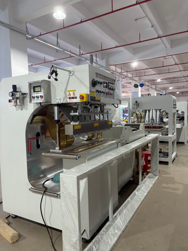
A travelling head HF welder moves along the seam on wheels or guide rails while the generator and press remain stationary or follow on a separate cart. The welding head clamps the overlapping membrane edges between a pair of roller electrodes. RF energy fuses the coating as the rollers advance, creating a continuous seam at speeds between 0.5 and 3 meters per minute.
Key features that matter on a tropical job site include:
- Adjustable roller pressure to accommodate varying membrane thickness and scrim density
- Automatic frequency tuning that compensates for changes in material moisture and ambient temperature
- Sealed electronics enclosures that prevent dust and humidity ingress during monsoon season work
- Integrated air‑tightness test channels that allow on‑the‑spot seam verification
Operators in the field position the membrane, align the overlap, and guide the welder along the joint. Tension control on the feed‑in and take‑up sides prevents wrinkles that create leak paths. Welding under direct sun requires cooling periods for the generator; early morning and late afternoon shifts often deliver the most consistent results in tropical climates.
2.2 Factory Prefabrication with Large Table HF Machines
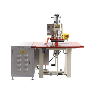
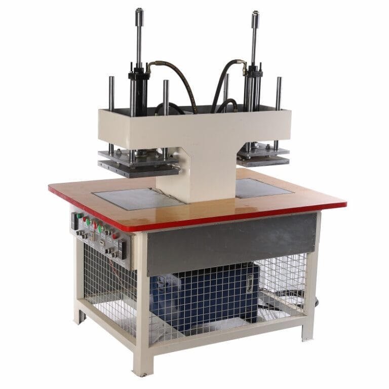
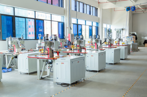
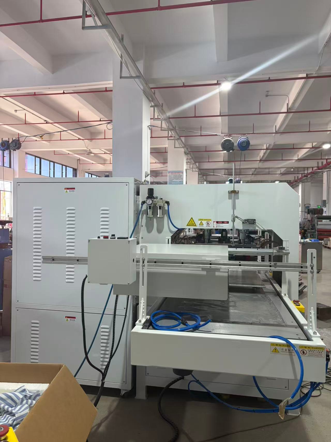
Some projects prefabricate large panels indoors, ship them to the site, and complete only the final panel‑to‑panel tie‑ins in the field. A large table HF welder handles this factory phase. The full panel lies flat on a wide platen, and an overhead press descends to weld long linear seams in a single cycle.
Advantages of factory prefabrication include:
- Controlled environment eliminates wind, dust, and humidity variables
- Larger weld area per cycle produces panels faster than any travelling head
- Multi‑cavity tooling can simultaneously attach anchor flaps, boots, and pipe penetration seals
The trade‑off is panel size limited by transport logistics. Most projects combine both methods: factory‑welded panels delivered in 40‑foot container‑sized rolls, with field‑welded tie‑ins completing the installation.
3. Seam Integrity Testing and Quality Assurance
A geomembrane seam carries legal and environmental liability. Every joint must be tested, documented, and accepted before the liner goes into service. Two complementary methods provide the required assurance.
3.1 Destructive Peel and Shear Testing
Sample welds made at the start and end of each shift, and at regular intervals during the day, undergo destructive testing on‑site. A portable tensiometer peels the welded strip apart and records the force. The failure mode matters as much as the number. A properly welded seam tears through the coating or breaks the scrim. Separation at the bond interface, with clean, un‑torn surfaces, indicates incomplete fusion and an immediate stop‑work condition.
A parallel shear test pulls the two sheets in opposite directions across the weld plane. Industry standards such as ASTM D6392 and GRI‑GM19 specify minimum peel and shear values that vary by membrane thickness. A 1.5‑millimeter PVC geomembrane typically requires peel strength above 15 N/cm and shear strength above 150 N/cm.
3.2 Non‑Destructive Air‑Pressure Testing
Every inch of field‑welded seam also receives a non‑destructive air‑tightness test. The travelling welder often creates a small enclosed channel between two parallel weld lines. A needle connected to a compressed air source pressurizes this channel, and a gauge monitors pressure decay.
- Pressurize the channel to the specified test pressure, typically 200 to 250 kPa
- Hold for a minimum of 30 seconds
- A pressure drop of more than 10% indicates a leak; mark the location and re‑weld
Operators walk the entire seam line with the test needle, pausing at intervals to verify the reading. Any detected leak triggers immediate repair with a hand‑held hot‑air gun or a local patch welded under the same HF parameters.
⚠️ CRITICAL NOTICE: Always ground the HF generator to a dedicated earth rod before starting any field welding operation. Geomembrane installation sites are often exposed and subject to lightning. A generator left ungrounded during an electrical storm can arc through the electrode and destroy both the machine and the liner section under the press. Disconnect power and cover the equipment when storms approach.
4. Conclusion
Geomembrane installations across Southeast Asia, from shrimp ponds in Thailand to landfill caps in Vietnam, rely on HF‑welded seams to contain water, waste, and gas for decades. An HF geomembrane welder fuses the thermoplastic coating from within, creating a bond that becomes part of the material rather than a separate layer sitting on top. Travelling‑head machines bring that fusion capability directly to the field. Factory‑based large‑table machines prefabricate panels with speed and consistency. Together they form a system that combines production efficiency with the seam integrity that environmental regulations demand.
The test data backs every joint. Peel samples break in the parent material, not at the weld. Air‑pressure tests hold steady across kilometers of seam line. A properly executed HF welding program for geomembranes delivers not just a sealed liner but a documented, defensible installation that satisfies both the engineer and the regulator. That is the standard to which every large‑format liner project should be built.