High Frequency Welder Water Cooling Maintenance: Why RF Welder Distilled Water Matters and How Cooling Failure Cascades Through Your Machine
Heat is the unavoidable byproduct of every HF weld cycle. The generator produces it. The press electrodes absorb it. The material releases it. The HF welding machine cooling system carries that heat away from sensitive components and rejects it to the ambient air through a chiller or heat exchanger.
When the cooling system works, nobody notices it. When it fails, the consequences cascade rapidly. A restricted water line starves an electrode of cooling. The electrode overheats. The material scorches. The die warps. The generator tube or solid state module runs beyond its rated temperature. Component life shortens from years to hours. Production stops.
Proper high frequency welder water cooling maintenance prevents this cascade. This guide explains how to flush and refill the cooling system, what water quality the system requires, how to inspect hoses and verify flow, and what happens when cooling fails.
Why Distilled Water Is Not Optional
Tap water, well water, and even filtered municipal water all contain dissolved minerals. Calcium, magnesium, iron, and silica dissolve invisibly in the water supply. Inside a cooling system, these minerals precipitate out onto hot surfaces.
The hottest surfaces in the system are the electrode cooling passages and the generator tube anode jacket. Mineral scale deposits on these surfaces act as thermal insulation. Heat transfer efficiency drops. The component runs hotter even though the water temperature and flow rate remain unchanged. The operator sees no alarm. The component slowly cooks itself to death.
Scale also restricts flow passages. A cooling channel designed with a 6-millimeter diameter can narrow to 3 millimeters or less after months of scale deposition. Flow rate drops. The temperature differential across the component increases. Localized boiling can occur at the hottest spots, which accelerates scale formation further.
RF welder distilled water or deionized water contains essentially zero dissolved solids. It cannot deposit scale because it carries nothing to deposit. This single specification extends the life of every water-cooled component in the machine by preventing the primary cause of cooling system degradation.
Use distilled water, deionized water, or reverse-osmosis purified water. Never use tap water, even temporarily. The few dollars saved on water cost will be repaid hundreds of times over in component replacement expense.
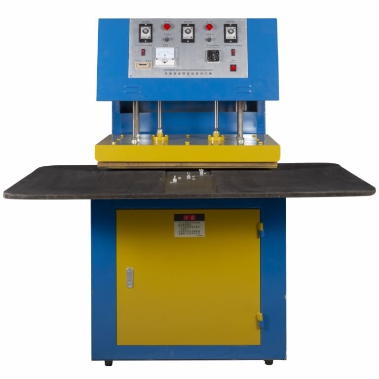
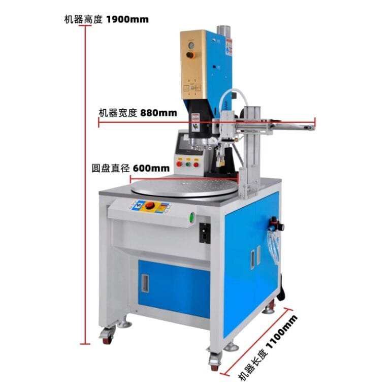
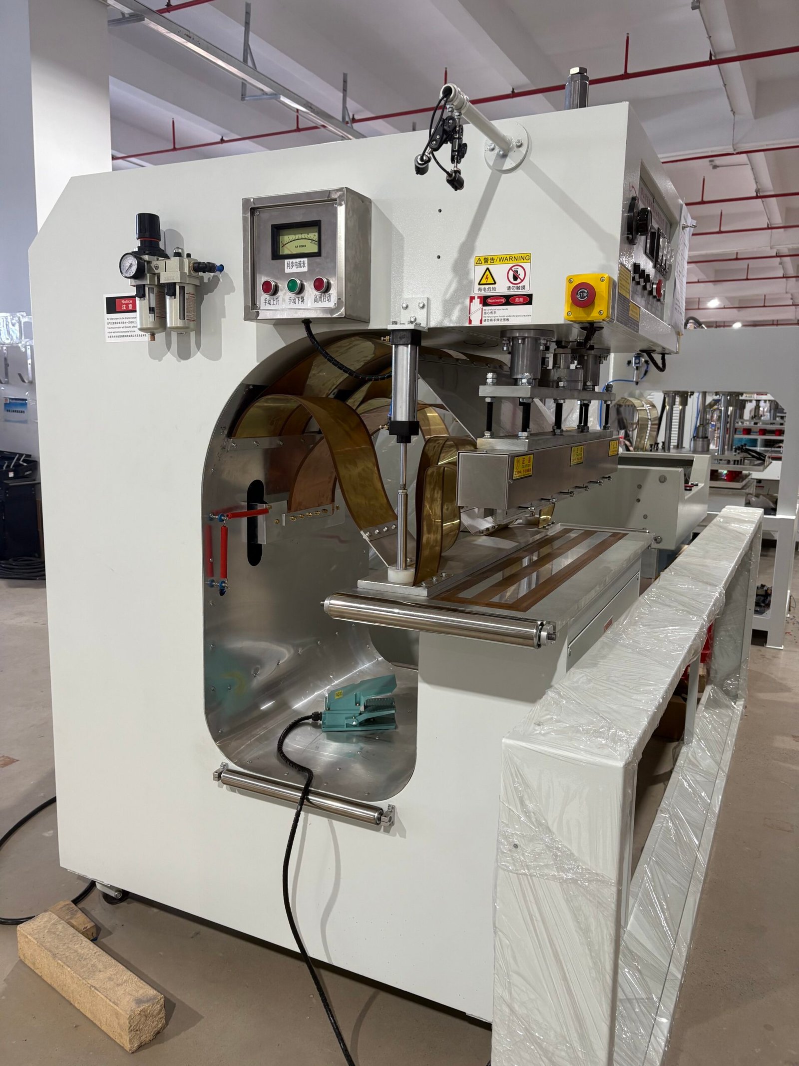
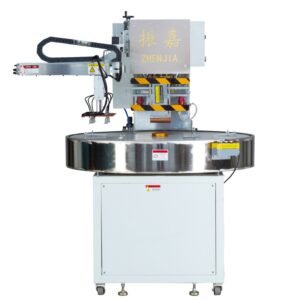
related products
Cooling System Flush Procedure
Flushing removes accumulated contaminants, scale, biological growth, and degraded coolant from the system. A proper HF welder cooling system flush follows a specific sequence to ensure all old fluid and debris exit the system.
Flushing Frequency
Flush the cooling system at least once per year. Machines running in hot climates or operating three shifts per day benefit from flushing every six months. Flush immediately if the coolant appears cloudy, discolored, or contains visible particles. Flush whenever a major component such as a tube, electrode, or heat exchanger is replaced. The new component should not inherit contamination from the old system.
Preparation
Power down the machine completely. Follow the full lockout procedure. The cooling system may contain hot water under pressure. Allow the machine to cool until all components are safe to touch. Locate the system drain points. Most machines have a low-point drain valve on the reservoir or the pump inlet. Some have additional drain plugs on water-cooled manifolds.
Place a catch basin under each drain point. Have adequate containers ready. The system volume for a typical 10kW to 15kW machine ranges from 10 to 30 liters. Know your system capacity before opening the first drain.
Draining the Old Coolant
Open the reservoir fill cap to break the vacuum lock. Open the main drain valve and allow all coolant to drain into the catch basin. And Open any additional drain plugs at low points on water manifolds and electrode cooling circuits. Tilt or blow low-pressure compressed air through the system to displace trapped water in hidden pockets.
Inspect the drained coolant. Clean coolant that has been properly maintained should look clear with perhaps a slight color from the anti-corrosion additive. Cloudy, rusty, or green-tinged coolant indicates corrosion, scale particles, or biological growth. The presence of these contaminants confirms the flush is overdue.
Flushing with Clean Water
Close all drain points. Fill the system with clean distilled water. Do not add coolant or inhibitors at this stage. Run the circulation pump for 10 to 15 minutes with the RF generator off. The water circulates through all passages and picks up residual contaminants.
Drain the flush water completely. Inspect it. If it carries visible discoloration or particles, repeat the flush cycle with fresh distilled water until the drained water runs clear. Stubborn systems with heavy scale or biological fouling may require a commercial cooling system cleaner. Follow the cleaner manufacturer’s instructions and flush thoroughly with distilled water after chemical cleaning to remove all cleaner residue.
Refilling with Fresh Coolant
Close all drain points. Prepare the fresh coolant mixture. Use distilled water as the base. Add the correct concentration of corrosion inhibitor and biocide specified by your chiller or machine manufacturer. Typical inhibitor concentrations range from 5% to 20% by volume. Do not over-concentrate. Too much inhibitor can reduce heat transfer and cause pump seal damage.
Fill the reservoir to the indicated level. Run the circulation pump and watch the reservoir level. It will drop as water fills the distribution piping and component passages. Top up until the level stabilizes at the correct fill mark. Bleed air from any high-point vent valves. Trapped air blocks flow and creates hot spots.
Run the machine with the RF off for 15 to 30 minutes. Watch the flow meter and the temperature gauge. Verify that flow is steady and temperature rise across the system is within normal limits. Check every fitting, hose connection, and drain plug for leaks. Tighten any leaking connections.
Water Quality Standards for Long-Term Reliability
Maintaining proper water quality between flushes extends component life and reduces maintenance frequency. Test the coolant at least quarterly with a conductivity meter and pH test strips.
Conductivity measures the dissolved ion content. Distilled water starts with conductivity below 5 microsiemens per centimeter. As the system runs, it picks up ions from component surfaces and from air absorption. Conductivity rises over time. When conductivity exceeds 50 microsiemens per centimeter, the coolant is due for replacement. High conductivity promotes corrosion and can create conductive paths that compromise electrical safety in water-cooled high-voltage components.
pH measures acidity or alkalinity. The coolant should maintain a pH between 7.0 and 8.5. Acidic coolant with pH below 7.0 corrodes copper, brass, and steel components. Alkaline coolant with pH above 9.0 promotes scale formation. The corrosion inhibitors in the coolant mixture buffer the pH and keep it stable. Falling pH indicates inhibitor depletion. The coolant needs replacement.
Visually inspect the coolant in the reservoir weekly. Clear, clean coolant indicates a healthy system. Cloudiness, discoloration, floating particles, or any sign of oil on the water surface requires investigation. Oil in the coolant often indicates a failing pump seal.
Hose Inspection and Replacement
Cooling hoses do not last forever. They degrade from heat, pressure cycling, and chemical exposure. A failed hose dumps coolant into electrical enclosures or onto hot surfaces, causing damage far beyond the cost of the hose itself.
Inspect every cooling hose during the annual flush. Look for surface cracks, especially at the ends where the hose stretches over barbed fittings. Squeeze the hose along its length. It should feel resilient and spring back. A hard, stiff hose has lost its plasticizer and is at risk of cracking. A soft, spongy hose has degraded internally and may collapse under suction, blocking flow.
Check hose clamps for tightness and corrosion. Stainless steel clamps resist rust. Plain steel clamps rust and fail, especially in the humid environment near a chiller. Replace all plain steel clamps with stainless steel.
Replace any hose that shows cracking, hardening, softening, or internal collapse. And Replace all hoses proactively every three to five years even if they appear sound. The cost of a complete hose set is trivial compared to the downtime and damage caused by a single burst hose.
Flow Meter Verification
The flow meter or flow switch is the only real-time indicator that cooling is actually happening. A faulty meter that reads flow when none exists allows the machine to run without cooling until a component fails from overheating.
Verify flow meter accuracy during the flush procedure. Fill and circulate the system normally. Note the flow reading. Disconnect the return line at the reservoir and direct it into a calibrated container for a measured time interval, such as 30 seconds. Measure the volume collected. Calculate the actual flow rate in liters per minute. Compare it to the meter reading.
A meter reading within 10% of the measured value is acceptable. A larger deviation indicates a meter that needs calibration or replacement. If the meter reads flow but no water moves, the meter has failed internally. Replace it before returning the machine to service.
Verify that the flow switch trips at the correct low-flow threshold. Slowly close a valve downstream of the flow switch while the machine runs with RF off. Note the flow rate at which the switch opens and the machine alarms. This should match the minimum flow specification for your machine. A switch that fails to trip at the specified low-flow point provides no protection.
The Chain Reaction of Cooling System Failure
Understanding what happens when cooling fails motivates diligent welding machine heat management. The failure cascade follows a predictable sequence.
The initiating event is usually a flow restriction. A kinked hose, a clogged strainer, a failed pump, or a closed valve reduces water flow to one component or the entire system. The component temperature begins to rise. The temperature rise is initially undetectable at the operator station because most machines do not monitor individual component temperatures.
The overheated component enters thermal runaway on the next high-power weld cycle. For an electrode, the hot surface scorches the material. The operator may increase power to compensate for what appears to be a cold weld, which overheats the electrode further. For a vacuum tube, the anode glows beyond its rated dissipation. The glass envelope softens or cracks. Air enters the tube and it fails instantly.
If the tube survives the initial overheat, the coolant trapped in the anode jacket boils. Steam pressure spikes. A hose blows off its fitting. Hot water and steam spray into the generator cabinet. High-voltage components short circuit. The main breaker trips, but only after extensive water damage to transformers, rectifiers, and control circuits.
This entire cascade from initial flow restriction to catastrophic failure can occur within minutes. It is prevented by the simple, scheduled maintenance procedures described in this guide.
Integrating Cooling Maintenance into the Overall Machine Schedule
Cooling system maintenance should align with the maintenance calendar established for the rest of the machine. The annual flush and hose inspection coincides with the annual machine overhaul. Quarterly water quality tests coincide with quarterly electrical safety checks. Weekly reservoir inspections coincide with weekly air filter cleaning.
Document every flush, fill, test, and hose replacement in the machine maintenance log. Record the coolant type, inhibitor concentration, and the name of the person performing the work. This log provides traceability and helps diagnose future problems.
A well-maintained high frequency welder water cooling system operates silently and reliably. It keeps electrodes cool, generators stable, and production running. Ten liters of distilled water and an hour of scheduled maintenance once a year prevent the catastrophic, expensive failures that happen when cooling is neglected until it fails.