 TEL +86-13923172919
HF Welding Weld Ripples and RF Welding Pinholes Seam: How to Fix High Frequency Welding Surface Defects on Pipe and Push Plate Machines
Surface defects on an HF-welded seam tell a clear story to anyone who knows how to read them. A ripple pattern speaks of mechanical instability. A pinhole whispers of trapped gas or a tiny arc. A surface pit shouts of contamination or localized overheating. Each flaw betrays a specific process failure waiting to be corrected.
High frequency welding surface defects do more than ruin appearances. Ripples create stress risers that initiate tears. Pinholes breach airtight seals. Pits weaken the seam cross-section and trap contaminants. Left unchecked, these HF weld quality problems increase scrap, trigger warranty claims, and erode production margins.
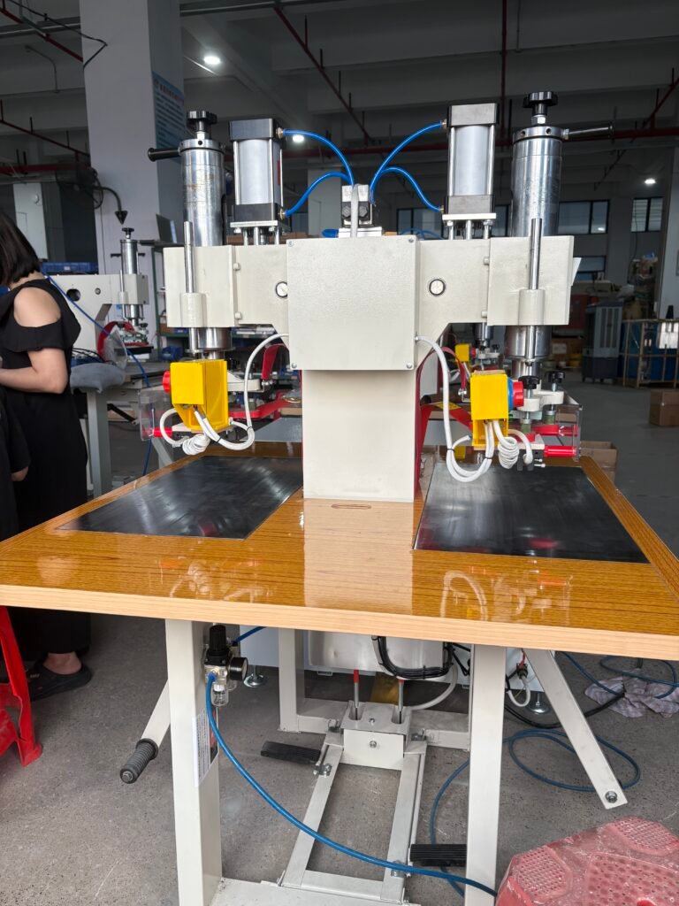
This article examines the three most common surface defects on HF-welded seams. It explains the specific cause behind each pattern and provides the adjustment that eliminates it. We address both HF Pipe Welding Machine setups, where guide roll positioning and V‑angle control dominate, and Push Plate HF Welding Machine applications, where die alignment and pressure uniformity rule.
Weld Ripples: When Mechanical Instability Prints Waves into the Seam
HF welding weld ripples appear as regular, wave‑like ridges running across the weld bead. Run your finger along the seam and you feel a corrugated surface. These ripples form when the molten material at the weld point does not flow into a smooth, continuous pool. Instead, it pulses or chatters as it solidifies.
Ripples almost never originate in the RF generator. They trace back to the mechanical components that position and move the material. Fix the mechanics and the ripples disappear.
Cause 1: Incorrect V‑Angle Opening
The V‑angle defines the gap between the two material edges as they approach the weld point. An opening that is too wide permits the edges to vibrate or flutter before they meet. This flutter modulates the amount of material entering the weld zone, creating alternating thick and thin spots that set as ripples. An opening that is too narrow forces the edges together prematurely, starving the apex and producing a similar unstable flow.
The fix: Measure the V‑angle at the point where the edges first touch. On most thermoplastic tube and sheet applications, an angle of 4 to 7 degrees delivers stable edge presentation. Adjust the angle by moving the guide rolls closer to the weld point or by modifying the forming fins. On a HF Pipe Welding Machine, this adjustment directly controls edge stability. Narrow the gap until the material feeds smoothly without visible side‑to‑side vibration. A stable, silent V‑shape eliminates the mechanical source of ripples at the root.
Cause 2: Misaligned Guide Rolls or Squeeze Rolls
Guide rolls set the edge height and lateral position just before welding. A single roll offset by half a millimeter forces one edge to ride higher than the other. The weld must then bridge a vertical step, and the bridge solidifies as a continuous ripple. Worn roll bearings introduce periodic vibration. Each bearing oscillation prints a matching wave into the cooling weld bead.
The fix: Check every guide roll position with a dial indicator referenced to the weld centerline. Roll faces must sit parallel to the strip surface and perpendicular to the machine axis. Replace any roll with detectable bearing play immediately. On a HF Pipe Welding Machine, verify that the squeeze rolls apply equal pressure from both sides and that their axes align perfectly with the tube center. Lock all adjustment mechanisms after positioning and re‑measure after the first hour of production. A well‑aligned roll set produces a bead with no periodic surface pattern.
Cause 3: Inconsistent Squeeze Pressure
Insufficient squeeze pressure fails to consolidate the molten edges into a dense, homogeneous bead. The material freezes before the edges fully knit, leaving a rippled surface. Excessive pressure squeezes out too much melt and creates a sunken centerline that mimics a ripple.
The fix: Adjust the squeeze pressure until the weld bead exhibits a slight, even crown on both the inside and outside surfaces. Start at the low end of the pressure range recommended for your material and thickness. Increase pressure in small steps, observing the bead profile after each change. On a Push Plate HF Welding Machine, the die pressure and platen parallelism serve the same consolidating function. Verify that the die closes evenly across its full length. The correct pressure produces a smooth, uninterrupted bead surface free of waves.
Cause 4: Fluctuating Line Speed or RF Power
If the drive speed hunts or the generator output oscillates, the heat delivered per millimeter of weld length varies. This thermal cycling expands and contracts the melt pool volume in a repeating pattern that solidifies as ripples.
The fix: Measure line speed with a contact tachometer over a full production cycle. The reading must stay within 1% of the setpoint. Service worn drive motors, slipping belts, or faulty speed controllers. On the generator side, engage the automatic power regulation circuit. A PLC controlled HF welder with closed‑loop power control eliminates power‑related ripples by maintaining constant output regardless of incoming voltage swings.
Pinholes: Tiny Holes That Destroy Airtight Integrity
RF welding pinholes seam defects show up as small, crater‑like perforations through the weld bead. In clear materials, you see them as trapped bubbles along the seal line. A single pinhole turns a leak‑proof product into a reject. Medical pouches fail integrity testing. Inflatable products go flat overnight. Pinholes demand immediate shutdown and correction.
Cause 1: Overheating and Material Degradation
Excessive RF energy pushes the material temperature beyond its degradation threshold. The polymer decomposes, releasing gas bubbles. These bubbles burst through the molten surface and leave pinholes behind. The seam may look fully fused, but the holes make it functionally useless.
The fix: Reduce RF power or shorten weld time. The correct energy input produces a full‑strength weld without discoloration or bubble formation. Perform a peel test on every setup change. A correctly welded seam tears through the parent material, not along the bond line. If the seam separates with a brittle crack or shows brown discoloration, reduce power in 10% steps until the pinholes vanish and the peel test still passes. This addresses the most common HF weld quality problems related to over‑welding.
Cause 2: Moisture and Volatile Contaminants
Hygroscopic materials like nylon, PET, and certain PVC compounds absorb moisture from ambient air. During welding, this moisture flashes into steam. The steam bubble expands violently, breaches the melt surface, and leaves a pinhole. Residual solvents, oils, and plasticizer bloom create the same effect.
The fix: Store material in a dry, temperature‑controlled environment. Pre‑dry hygroscopic materials per the supplier’s recommendation, typically 2 to 4 hours at 60°C to 80°C. Clean material surfaces with isopropyl alcohol and a lint‑free wipe immediately before loading. This step is critical on a Push Plate HF Welding Machine producing medical pouches, where any trapped contamination generates pinholes that fail ISO 11607 seal integrity standards.
Cause 3: Contaminated or Arcing Electrodes
A dirty die face creates localized electric field concentrations. These hot spots vaporize both the contaminant and the surrounding polymer. The resulting arc pit often penetrates through the material as a pinhole. The weld pit HF welding machine connection is direct: a pitted die stamps a defect into every part that follows.
The fix: Establish a scheduled die cleaning interval based on cycle count, not on when defects appear. Use a fine brass brush or non‑woven abrasive pad to remove residue. Wipe the sealing face with isopropyl alcohol. If pitting is already present, resurface or replace the die. Activate the arc detection and suppression circuit on the generator to halt the cycle at the first spark and prevent cascade die damage.
Cause 4: Insufficient Weld Pressure
Low pressure allows gas bubbles to nucleate and grow inside the melt. The bubbles remain trapped because the surrounding material never compresses them into solution. When the material solidifies, the bubble cavities remain as pinholes.
The fix: Increase press pressure until a small, continuous flash bead appears on both sides of the seal. This flash indicates adequate consolidation pressure. Observe the flash under magnification. A smooth, continuous flash suggests effective bubble evacuation. A foamy or discontinuous flash warns of trapped gas still present in the melt. Adjust pressure upward until the flash runs clean.
Surface Pits: Depressions That Weaken and Disfigure the Seam
Surface pits appear as small, irregular depressions that do not penetrate fully through the material. They spoil the product appearance and act as stress concentrators where tears can initiate under load. Pits arise from several distinct mechanisms.
Cause 1: Embedded Foreign Particles
A dust speck, a fiber fragment, or a trimmed flash chip landing on the material before welding absorbs RF energy differently from the surrounding polymer. The particle chars, shrinks, or bonds weakly. It later detaches, leaving a pit.
The fix: Create a clean zone around the welding station. Use ionized air blowers to neutralize static charges that attract dust. Install tacky rollers or brushes on the material infeed path. On a HF Pipe Welding Machine, enclose the strip feed path to prevent airborne debris from settling on the material. A clean infeed eliminates random pitting events.
Cause 2: Micro‑Arcing at Die Edges
Even a tiny arc etches a shallow crater into the material surface. Unlike full‑penetration pinholes, these micro‑arcs are brief enough that surrounding melt partially refills the crater. The result is a shallow pit with a discolored, carbonized base. Micro‑arcing concentrates at sharp die corners where the electric field intensifies.
The fix: Break all sharp edges on the die sealing profile. Add a radius of at least 0.5mm to sealing edge corners. Confirm that the die face sits perfectly parallel to the counter electrode using pressure‑sensitive film. Tune the arc suppression circuit to respond at the lowest detectable discharge level. Preventing arcs is the only permanent solution to arc‑related pitting.
Cause 3: Material Inhomogeneity
Poorly dispersed fillers, pigment agglomerates, or gelled particles in the compound absorb RF energy at a different rate than the matrix. The inclusion overheats, degrades, and falls out, leaving a pit. Batch‑to‑batch material variation often triggers sudden pitting outbreaks on a previously stable process.
The fix: Test every incoming material batch with a small production run before full‑scale use. If pitting appears on a new batch while machine parameters remain unchanged, quarantine the batch and notify the compound supplier. Improve incoming material inspection to include dispersion quality checks. For in‑house compounding, increase mixing shear or time to break down agglomerates.
Cause 4: Premature Release of Cooling Pressure
If the press opens before the material solidifies completely, the still‑soft surface sinks slightly as it cools in free air. This creates broad, shallow depressions rather than sharp pits. The defect pattern repeats identically with the cycle timing.
The fix: Extend the cooling time parameter in the PLC. The material must cool below its softening point before the die retracts. On a Push Plate HF Welding Machine, increase cooling time in 0.5‑second increments until the pits vanish. Verify that cooling water flows adequately through the electrodes. Restricted flow extends the required cooling duration and allows heat to build up over consecutive cycles.
Integrated Approach to Eliminating Surface Defects
Solving high frequency welding surface defects permanently requires a structured approach. Begin by identifying the defect type from its visual signature. Match the signature to the most likely cause from the lists above. Make one adjustment at a time and test the result before moving to the next variable. Document every parameter change and its effect.
Implement a preventive inspection routine. Check guide roll alignment weekly. Clean dies at a fixed cycle interval. Verify cooling water flow daily. Train operators to recognize the early signs of ripple, pinhole, and pit formation and to report them immediately. A defect caught on the first part of a shift saves an entire day of scrap production.
The difference between a perfect seam and a rejected one often measures in fractions of a millimeter of roll position or tenths of a second of weld time. Methodical diagnosis closes that gap and keeps your HF weld quality problems in the history books where they belong.