How to Use a High Frequency Welding Machine for PVC Products: A Step-by-Step Setup Guide
PVC is the most responsive material in high frequency welding. Its strong molecular dipole absorbs electromagnetic energy efficiently, heats evenly from the inside out, and fuses cleanly under pressure. But a machine loaded with PVC still produces bad welds if the setup is wrong.
Most weld failures on a high frequency PVC welding machine trace back to one of five things: unleveled electrodes, incorrect pressure, mismatched power, insufficient cooling time, or material that was never prepared properly. Every one of these is preventable. This guide walks through the complete setup sequence so you can start making good welds from the first production cycle.
Before You Touch Any Settings: Understand Your Material
PVC is not a single material. It is a broad family of compounds. The base polymer is the same, but the plasticizer content, stabilizer type, and additive package vary significantly between suppliers, grades, and intended applications.
Flexible PVC film — the type used in medical bags, inflatable products, and stationery — responds quickly to HF energy and welds at relatively low power settings. Rigid PVC — used in blister shells, folding boxes, and profile components — has less plasticizer and a higher glass transition temperature. It takes longer to heat and generally requires either more power, longer weld time, or a heated electrode platen to produce a consistent bond.
Before setting any machine parameters, know the answer to three questions about your material: What is the nominal film thickness? Is it flexible or semi-rigid PVC? And does the supplier specify an HF-weldable grade? Some PVC grades are formulated specifically for RF welding and have documented dielectric loss properties. Others — particularly PVC films intended for print or lamination applications — may have additives that reduce their weldability or cause surface contamination problems.
If you cannot confirm weldability from the material datasheet, cut a small test piece and run it through the machine before committing to a full production setup. A weld that peels cleanly by hand with visible material fusion — not surface adhesion — confirms that your PVC grade is suitable.
Step 1 — Safety Checks Before Power-On
A high frequency PVC welding machine operates at 27.12 MHz and high voltage. Run through these checks every time before powering on, not just during first-time installation.
Verify grounding. The machine chassis must be properly grounded to a dedicated earth connection. If the RF ground becomes isolated from the chassis ground — due to corrosion, a loose terminal, or a missing connection — a potential difference builds up between the electrode and the frame. This causes arcing inside the machine and creates a real electrocution risk for the operator. Inspect the ground connection visually at the start of each shift. Do not operate the machine if grounding cannot be confirmed.
Check door and panel interlocks. All cabinet doors and access panels should trigger an automatic shutdown if opened during operation. Test each interlock switch before starting. Never bypass or jumper out an interlock. If a switch has failed, shut down the machine and replace it before resuming production.
Inspect the electrode surface. Look for carbon deposits, burn marks, pitting, or residue from previous production runs. A contaminated electrode concentrates the electromagnetic field unevenly, causing localized overheating and increasing arc risk. Wipe the electrode surface with a clean, dry cloth. For heavier contamination, use a soft brass wire brush. Never use steel wool or abrasive compounds, which leave conductive residue.
Check the backup material on the lower table. Every high frequency PVC welding machine uses a backup layer between the PVC and the lower metal table. This layer serves three functions: thermal insulation (keeps heat in the material rather than draining into the table), electrical insulation (reduces arc risk), and mechanical protection (prevents the PVC from sticking to the metal surface). Common backup materials include cardboard, Teflon sheet, felt, and purpose-made dielectric pads. Replace worn or contaminated backup material before starting. A degraded backup material is one of the most commonly overlooked causes of inconsistent welds and recurring arcing problems.
Confirm air pressure supply. Most HF welding machines use a pneumatic press. Check that compressed air is connected, that the line pressure meets the machine’s specification (typically 5 to 7 bar supply, with regulated working pressure set at the machine), and that there are no hose leaks or kinked lines.
Step 2 — Install and Level the Electrode
Install the welding die — the shaped electrode that defines the weld profile — according to the manufacturer’s mounting procedure for your machine. Tighten all mounting fasteners to the specified torque and confirm that the die is fully seated in the electrode holder.
Now level the electrode. This step is non-negotiable and must be repeated every time you change dies.
An electrode that sits even slightly unlevel applies different pressure across the die surface. The side with higher contact pressure fuses properly. The side with lower pressure sees an air gap between material layers. In that air gap, the electromagnetic field concentrates, voltage breakdown occurs, and arcing follows. What looks like a power problem is almost always an alignment problem.
Place a flat sheet of PVC on the lower table. Lower the electrode slowly by hand — not under power — until it just contacts the PVC surface across its full width. If the contact is uneven, adjust the leveling screws at the electrode mounting plate until contact is uniform. Check both the front-to-back and left-to-right alignment. Reconfirm after tightening the final fasteners, as tightening often shifts the position slightly.
On some machines a depth of sink control limits how far the electrode can descend after the PVC begins to melt. Set this control so the electrode stops at the correct final weld thickness for your product. For plain lap welds in standard flexible PVC, the correct sink depth typically results in a weld thickness of approximately 60 percent of the total original material thickness. This is a general guideline — your specific product and material may require adjustment.
Step 3 — Place the Backup Material and Load the PVC
Lay the backup material flat on the lower table and smooth out any wrinkles. Wrinkles in the backup material create pressure variations across the weld area and produce uneven seams.
Place your PVC layers on top of the backup material. Align the layers carefully so the weld zone sits directly under the die. For products with dimensional requirements — medical bags, stationery pockets, automotive components — use alignment pins, stops, or fixtures to ensure consistent positioning on every cycle.
Keep the PVC surface clean. Oil from hands, dust, mold release agent residue from thermoformed blisters, and moisture from humid storage all interfere with molecular bonding. Wipe the PVC surface with isopropyl alcohol if contamination is visible, and allow it to dry completely before welding. Moisture on the surface is not immediately obvious to the eye but causes bubbling and pinholes in the finished weld.
For products that require welding different PVC thicknesses together — for example, a thick PVC connector sealed into a thin film bag — add a strip of buffer material on the thin-material side. This buffer equalizes the heating rates of the two layers. Without it, the thinner material heats faster, softens first, loses clamping force at the bond surface, and the joint fails to fuse completely across its full width.
Step 4 — Set Press Pressure and Depth Stop
Set the press pressure using the machine’s pneumatic regulator. Pressure controls how firmly the electrode presses into the PVC during and after welding.
The correct pressure allows the electrode to sink smoothly into the PVC as the material softens — without forcing it through the material before fusion is complete. Pressure that is too low creates an air gap at the bond interface, raises the electromagnetic field intensity in that gap, and triggers arcing. Pressure that is too high pushes the electrode to the bottom of its travel before the material has fully softened, producing a thin, weak weld with visible squeeze-out at the edges.
A widely cited starting point for flexible PVC film is 1 to 2 kg/cm² of die contact pressure, measured across the actual electrode surface area. This translates to different pneumatic line pressures depending on your cylinder bore size. Use the machine’s specification sheet to calculate the correct air pressure for your die size rather than guessing from the regulator dial alone.
Once pressure is set, adjust the depth stop to limit electrode travel. This stop acts as a mechanical backstop that prevents the electrode from sinking beyond a set depth regardless of the air pressure. Set it conservatively — slightly shallower than your target weld thickness — and adjust forward in small increments during test welding.
Step 5 — Set HF Power Output
Power output controls the intensity of the electromagnetic field and therefore how quickly the PVC heats up. Setting power correctly is the step most new operators get wrong, because the intuitive response to a weak weld is to increase power — when the real problem is often weld time, not power level.
Start at a low to medium power setting. For flexible PVC film in the 0.3 mm range, a useful reference point from published data is approximately 250 to 300 watts per cycle for a 3-second weld time on a small die area. Scale this estimate upward proportionally for larger die surfaces or thicker materials.
Increase power gradually in small increments while running test welds until fusion is complete. The goal is the lowest effective power level — not the highest. Running at excessive power burns the material surface, increases electrode temperature, raises arcing risk, and wears out the die faster.
One important practical reality: the machine behaves differently cold versus hot. When the machine starts in the morning, the electrode is at room temperature. After 30 to 60 minutes of continuous production, the electrode retains significant heat from successive cycles. This pre-warming reduces the power needed per cycle. A setting that produces optimal welds at start-up may over-weld material once the electrode reaches its working temperature. Monitor the first hour of production carefully. Reduce power slightly as the electrode warms until it reaches a stable equilibrium, then maintain that setting for the rest of the shift.
On machines with automatic power control, the generator compensates for electrode temperature drift automatically. This makes production more consistent but does not eliminate the need to verify weld quality at the start of each shift.
Step 6 — Set Weld Time
Weld time is the duration the HF generator remains active. It directly determines how much energy enters the material. Weld time and power output are interdependent — increasing one allows you to decrease the other for equivalent energy input.
For standard flexible PVC film, weld times in the range of 2 to 5 seconds are typical for most production applications. Thicker materials, larger die areas, and materials with lower dielectric loss require longer weld times at equivalent power.
Set weld time conservatively and increase in 0.5-second increments during test welding. The weld is complete when the die has sunk to the depth stop and the PVC shows consistent fusion across the full weld area — no voids, no unbonded zones, and no surface burning.
Weld time that is too short produces a weak bond that peels easily. Weld time that is too long burns the material surface, melts through thin films, or causes the PVC to stick to the die. Both failures are immediately visible in a test weld — adjust one step at a time until the result is clean.
If your machine supports energy mode — where the generator runs until a preset amount of RF energy has been delivered rather than for a fixed time — use it. Energy mode compensates automatically for part-to-part material variation and electrode temperature drift. It produces more consistent welds across a long production run than fixed time mode on identical settings.
Step 7 — Set Cooling Time
Cooling time is the period the press holds pressure after the generator switches off. Heat drains from the fused PVC into the metal electrode, which acts as a heat sink. The material must solidify under pressure before the press opens.
Cooling time that is too short releases the material while it is still partially molten. The seam deforms under the residual heat, producing a joint that looks complete but has reduced peel strength and fails earlier under stress. For inflatable products, medical bags, and any application where the weld must hold under internal pressure, this is a critical failure mode.
A practical starting guideline: cooling time should be approximately 20 percent of weld time. A 4-second weld time suggests a starting cooling time of roughly 0.8 to 1 second. This ratio increases for thicker materials, larger thermal masses, and applications where dimensional stability of the weld area is critical.
Cooling time requirements also increase during sustained production as the electrode retains heat from successive cycles. A cooling time that produced solid welds at start-up may become insufficient after an hour of continuous operation. Check weld quality throughout a shift — not just at the beginning. If weld integrity degrades as the session progresses, increase cooling time before reducing power.
Step 8 — Run Test Welds and Evaluate Quality
Never commit production material to a first full run without test welds. Run at least five consecutive test welds before evaluating — the first cycle on a cold machine is always the most variable.
Evaluate each test weld using these checks:
Visual inspection. The weld seam should have a consistent width, clear edge definition, and no surface discoloration. A good weld on transparent PVC shows a slightly denser, uniform band along the seam. Burned edges, surface blisters, pitting, or a yellowish discoloration indicate too much power or too long a weld time. A seam that looks shiny but has no visible fusion at the edges indicates insufficient power or time.
T-peel test. Grip the unwelded material on either side of the seam and pull steadily apart at 180 degrees. On a properly welded PVC seam, the bond should be stronger than the base film — the material tears before the seam peels. If the seam opens cleanly with little force and shows smooth, glossy unbonded surfaces, the weld is incomplete. Adjust power or weld time and retest.
Dimensional check. Measure the weld seam width and verify it matches the die geometry. A narrower-than-expected seam suggests insufficient die contact pressure or shallow electrode travel. A wider seam with material flow outside the die boundary suggests too much pressure or excessive power.
Surface check after release. When the press opens, the weld should release cleanly from the die without sticking. If material adheres to the die surface, the weld temperature is too high, the cooling time is too short, or the backup material has degraded. Address each possible cause individually before resuming production.
Step 9 — Record the Parameters and Start Production
Once your test welds pass all quality checks, record the final settings: power level, weld time, cooling time, air pressure, and depth stop position. Store these as a named recipe in the machine’s PLC or control system if it supports parameter storage.
Writing settings down — even on paper — takes two minutes and saves significant time the next time you run the same product. PVC grade, supplier, film thickness, and die temperature all affect how the process performs, and settings from a previous successful run give you a validated starting point rather than starting from zero.
Begin production cautiously. Check every fifth weld against your visual and peel test standards for the first 30 minutes. After the electrode reaches its working temperature and the process stabilizes, reduce spot-check frequency. Increase it again if you switch to a new roll of PVC film, since material variation between rolls — even from the same supplier — can shift the optimum parameters slightly.
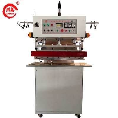
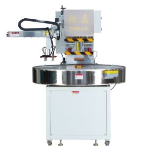
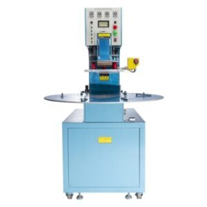
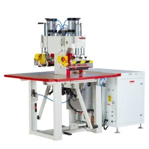
相关产品
Common Parameter Mistakes and How to Avoid Them
Increasing power to fix a weak weld before checking electrode level. Most weak welds on a high frequency PVC welding machine come from an air gap caused by an unlevel electrode — not insufficient power. Check level first. Adding power to a misaligned electrode makes arcing more likely without improving weld quality.
Setting cooling time as a fixed ratio of weld time and never adjusting it. The 20 percent rule is a starting point. It does not account for electrode heat buildup during a sustained production run. Monitor weld quality throughout each shift and adjust cooling time upward as the electrode warms.
Skipping the backup material or reusing a degraded pad. The backup layer is not optional. A missing or worn backup layer causes the PVC to lose heat into the metal table, concentrates the electromagnetic field at the edges of the die, and greatly increases arcing risk. Replace backup material at the start of each shift or whenever visible wear, contamination, or compression damage is present.
Running production on material that came straight from cold storage. PVC film at low temperature has different dielectric properties than PVC at room temperature. Allow cold-stored material to acclimatize to the production environment for at least two hours before welding. Cold PVC may require slightly higher power or longer weld time, but it is better to work with material at a known, stable temperature than to compensate for thermal variation.
Frequently Asked Questions
Why does my HF welding machine keep arcing on PVC?
Arcing on a high frequency PVC welding machine most commonly results from one of four causes: an air gap from an unlevel or misaligned electrode; excessive power relative to the material and die area; contamination on the electrode or PVC surface; or a missing, worn, or incorrectly positioned backup material. Work through each cause systematically. Start with electrode leveling, then check the backup layer, then reduce power. Do not increase pressure as a first response — this often makes arcing worse by creating uneven contact at the die edges.
How do I know if my PVC weld is strong enough?
The standard field test is the T-peel test: grip both sides of the seam and pull apart at 180 degrees. On a good weld, the base material tears before the seam opens. If the seam peels with a smooth, glassy surface showing unbonded zones, the weld is incomplete — increase power or weld time and retest. For products with critical seal requirements — medical bags, inflatable products, pressure vessels — supplement visual and peel testing with leak testing specific to the application.
What is the correct weld time for 0.3 mm flexible PVC?
Weld time depends on power level, die area, and electrode temperature — there is no single correct value. As a general starting point for standard flexible PVC at 0.3 mm thickness, a weld time of 2 to 4 seconds at medium power is a reasonable starting range. Run test welds, evaluate with the T-peel test, and adjust in 0.5-second increments. The right setting is the shortest weld time at the lowest power that consistently passes the peel test.
My welds are good at the start of the shift but deteriorate after an hour. What is happening?
This is a classic electrode temperature drift problem. As the electrode heats up during continuous production, it pre-warms each PVC charge before the generator activates. The effective energy delivered per cycle increases even though power and weld time settings remain constant. Reduce power slightly after the first 30 to 60 minutes and increase cooling time to compensate. On machines with automatic power control, the generator manages this drift internally, but weld quality monitoring throughout the shift remains good practice.
Can I weld PVC to TPU or PVC to PU on the same high frequency PVC welding machine?
Yes, but the setup requires more care than welding identical PVC layers. PVC and TPU have different glass transition temperatures. The machine heats both materials simultaneously, but the lower-Tg material softens first and may lose clamping force at the bond surface before the other material has fully fused. Add buffer material on the lower-Tg side to slow its heating rate and equalize fusion timing between the two layers. Start with lower power and longer weld time than you would use for PVC-to-PVC, and verify bond strength carefully with peel testing before committing to production runs.