 TEL +86-13923172919
HF Welding Die, Buffer, and Fixture Buyer Checklist
A factory producing double-sided APET blister packs or multi-layer TPU inflatable chambers often invests heavily in an 8kW or 15kW high-frequency welding machine, only to face burned edges, uneven peel strength, and frequent spark-protection trips during trial runs. In nearly every case, the generator is not the culprit—the tooling system is.
In industrial production, an HF welding die is not a standalone metal block you bolt onto the press as an afterthought. The upper electrode, cutting edge, lower RF welding fixture, dielectric buffer material HF welding layer, and press mounting interface work together as a single electrical and mechanical circuit. If one layer is mismatched, even a well-tuned PLC rotary or push-plate machine cannot hold consistent production quality.
Use this technical checklist before ordering tooling or finalizing machine specifications to treat your mold setup as an integrated process system.
1. Electrode Material Selection: Brass vs. Aluminum Die
The upper electrode delivers both mechanical clamping force and 27.12 MHz (or 40.68 MHz) alternating electromagnetic energy directly into the thermoplastic stack. Choosing between brass vs aluminum die construction depends on weld geometry, cutting requirements, and production volume.
| Evaluation Criteria | Brass Welding Die (Copper Alloy) | Aluminum Alloy Die (High-Strength CNC) |
| Electrical & Thermal Conductivity | Superior RF energy transfer and uniform heat retention across long weld seams | Good conductivity, dissipates heat faster into the upper platen |
| Tear-Seal & Cutting Edge Durability | High hardness and wear resistance; essential when welding and trimming simultaneously | Softer edge; cutting blades dull faster under repeated high-tonnage synchronous fusing |
| Machining & Weight | Heavier; higher material cost for large-format dies | Lighter; easier to CNC-machine for deep 3D cavities and large-area embossing plates |
| Best Production Fit | Synchronous fusing molds (APET/PETG/PVC blister cutting), sharp perimeter seals, high-cycle runs | Large-area automotive seat embossing, wide tarpaulin dies, multi-cavity locating fixtures |
- Synchronous Fusing (Cut-and-Weld) Systems: When processing eco-friendly APET, PETG, or GAG clamshell blisters on synchronous fusing presses (such as 15-ton to 20-ton booster cylinder models), the tooling must combine a flat sealing face with a precision-ground cutting blade. Brass dies or steel-rule-inserted brass electrodes are required to prevent edge burrs and maintain clean trimming over thousands of cycles.
- Heated Upper Platens: Many industrial HF presses incorporate integrated electric platen heating (adjustable from 50°C to 300°C). When welding semi-crystalline or low-loss polymers like PETG or thick EVA, preheating a brass die stabilizes interfacial melt and prevents cold joints.
2. Cutting Edge Geometry and Anti-Arcing Design
High-frequency energy concentrates along sharp metallic corners. Poor edge finishing on a custom high frequency welding mold is the leading cause of high-voltage arcing, which pits the electrode and burns holes through PVC or TPU films.
- Sealing Face Radius: Ensure all non-cutting edges of the welding bar have a smooth, radiused transition rather than a raw 90-degree burr.
- Tear-Seal Blade Offset: On tear-seal dies, verify the exact step height between the horizontal sealing land and the vertical cutting edge. If the cutting blade sits too proud of the sealing land, it will sever the plastic before the polymer molecules fully interdiffuse; if too shallow, operators must manually tear away excess flash.
- Venting & Air Escape: For enclosed inflatable chambers or multi-cavity medical pouches, verify that the die design allows trapped air to escape during initial clamping before RF discharge begins.
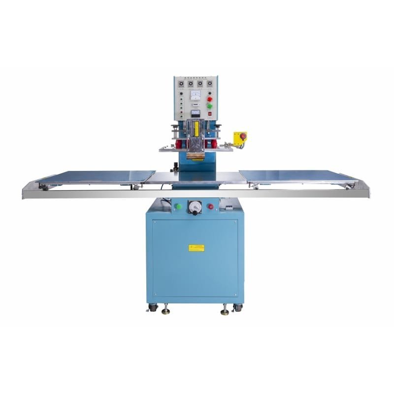
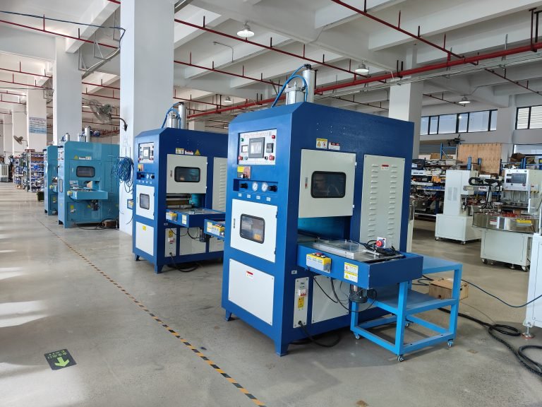
8KW Push-Type High Frequency Welder for PVC Bags
The 8KW High Frequency Welder is an industrial-grade solution designed for the precision sealing of PVC bags and thermoplastic products. Utilizing molecular oscillation technology, this push-type machine ensures hermetic, leak-proof bonds without the wrinkles or false welding associated with traditional heat pressing. Equipped with US-imported anti-spark protection, it safeguards your molds and materials during high-volume production cycles in demanding factory environments.
3. Dielectric Buffer Material and Lower Table Insulation
Between the lower aluminum worktable and the plastic workpiece sits the dielectric buffer layer (commonly phenolic Bakelite board, silicone-coated fiberglass cloth, or specialized high-temperature insulating sheets).
- Preventing Direct Short Circuits: In a synchronous fusing cycle, the cutting blade penetrates through the plastic film until it contacts the lower bed. Without a dedicated dielectric buffer layer, the energized upper die would make direct metal-to-metal contact with the grounded lower platen, triggering an immediate short circuit and damaging the oscillator tube or solid-state module.
- Thermal & Mechanical Stability: Buffer sheets must resist compression set under repeated clamping loads (ranging from standard pneumatic cylinders up to 15T–20T hydraulic/booster presses) and withstand platen temperatures up to 300°C without warping or carbonizing.
- Moisture & Contamination Control: Carbonized burn marks, adhesive residue, or absorbed factory humidity on buffer sheets create conductive paths. Operators must inspect and wipe buffer surfaces every shift and replace scored sheets immediately.
4. Lower RF Welding Fixture & Locating Architecture
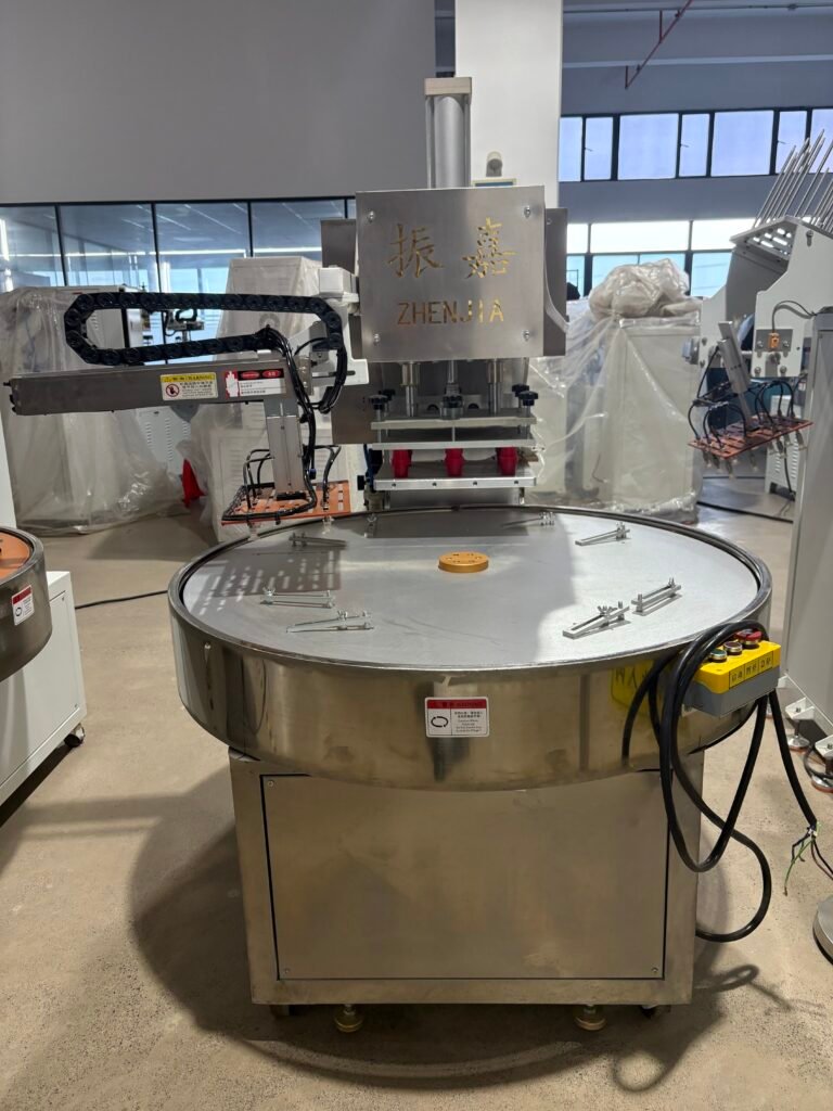
On single-head push-plate machines, double-head presses, and 3-station or 4-station rotary turntables, the lower RF welding fixture determines alignment speed and repeatability.
- Non-Conductive Fixture Materials: Lower positioning jigs that sit inside the active RF field must be machined from non-conductive, low-loss materials such as phenolic resin (Bakelite) or high-grade engineering plastics—never ungrounded metal pins that distort the electromagnetic field.
- Multi-Station Consistency: If you run a 3-station or 4-station rotary table (such as 1000 mm or 1200 mm diameter indexing discs), every lower mold on the turntable must match in height within ±0.05 mm. Height variance across stations causes uneven clamping pressure and inconsistent weld penetration from one index step to the next.
- Vacuum & Mechanical Demolding: For automated lines using vacuum pick-and-place manipulators to unload finished blister packs or pouches, the lower fixture should incorporate recessed vacuum channels or spring-loaded ejection pins so parts release cleanly without deforming warm weld seams.
5. Machine Mounting Interface & Changeover Compatibility
Before ordering a new mold—especially when adding an automated rotary machine alongside existing manual presses—confirm mechanical compatibility across your shop floor:
- Upper Platen Mounting Standard: Verify whether your press uses a cross-chuck clamp (common on double-head pedal and pneumatic machines) or a flat mounting platen with standard bolt-hole spacing (such as 100 mm, 310 mm, 350 mm, 480 mm, or 550 mm hole pitch). Matching mounting interfaces allows existing manual-press molds to transfer directly onto automatic rotary machines without re-machining.
- Maximum Lower Mold Footprint & Daylight Opening: Check both the lower worktable dimensions (e.g., 460 × 300 mm on compact 3-station rotary units vs. 1000 × 800 mm on heavy hydraulic push-plate presses) and the maximum electrode gap/stroke (typically 150 mm to 250 mm). Tall 3D products require sufficient daylight clearance so the tooling clears the workpiece during table rotation or slide shuttle movement.
- Sample Proofing Before Final Hardening: Whenever launching a new TPU formulation, multi-layer coated fabric, or complex APET tear-seal geometry, submit actual production material rolls to the tooling manufacturer for sample proofing. Testing the die on a matched kW press validates weld peel strength, cutting smoothness, and arc-suppression thresholds before mass production begins.
Mandatory Tooling Safety & Maintenance Boundaries
High-frequency dies operate at elevated temperatures and lethal RF/high-voltage potentials. Enforce these rules across all shifts:
- MUST verify that the upper electrode is securely locked into the cross-chuck or bolted flush to the upper platen before energizing the machine. A loose or tilted die creates uneven air gaps and severe electrical arcing.
- MUST confirm that the machine’s high-sensitivity spark protection circuit (arc suppressor) is active and calibrated whenever installing a new or resurfaced die.
- PROHIBITED: Never place hands, metal tools, or measuring gauges between the upper electrode and lower fixture while the press is powered on or in standby mode. Contact with an energized die causes deep internal RF burns, while platen heat controllers maintain surface temperatures up to 300°C.
- PROHIBITED: Never continue running production with a carbon-tracked buffer sheet or chipped cutting edge. Attempting to “push through” with higher RF current or longer weld timers will destroy the die face and overload the generator.
- NEVER perform mold changes, height shimming, or electrode cleaning without engaging mechanical safety blocks and isolating main electrical power.