Automatic High Frequency Welding Machine: How to Integrate HF Welding Into Your Production Line
A manual HF welding machine depends on an operator for every single cycle. The operator loads the material, triggers the press, waits for the weld, unloads the part, and repeats the process. This workflow works acceptably at moderate volumes. At high volumes, however, it turns into the primary bottleneck. The bottleneck does not come from the HF welding process itself, which completes in seconds. It comes from the cumulative human steps inserted between every weld cycle.
An automatic high frequency welding machine removes those manual steps from the critical path. It feeds, positions, welds, cools, and ejects parts in a continuous, synchronized loop. The system achieves cycle rates that no manually operated machine can sustain over a full shift. The result transforms production economics. You gain higher output, lower labor cost per unit, and consistent weld quality that does not drift with operator fatigue or shift changes.
This guide explains how manufacturers build automated RF welding system configurations. It shows how to connect the welder to the rest of the production line. It helps you assess when the investment makes clear economic sense and what to evaluate before committing to an automated setup.
What Makes a High Frequency Welding Machine “Automatic”
The term “automatic” covers a wide spectrum of configurations in industrial HF welding automation. Understanding the three main levels helps clarify exactly what your operation needs.
Semi-Automatic HF Welding: Machine-Controlled Cycle, Operator-Loaded Parts
This represents the entry point to automated HF welding. The operator loads parts and positions them in the fixture. The machine then handles the rest. It controls the press descent, HF power generation, cooling time, and press retraction automatically. It executes all these steps according to stored PLC parameters. The operator does not need to hold or guide the material at any point during the active cycle.
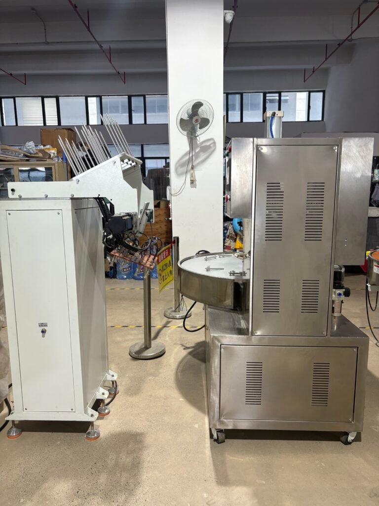
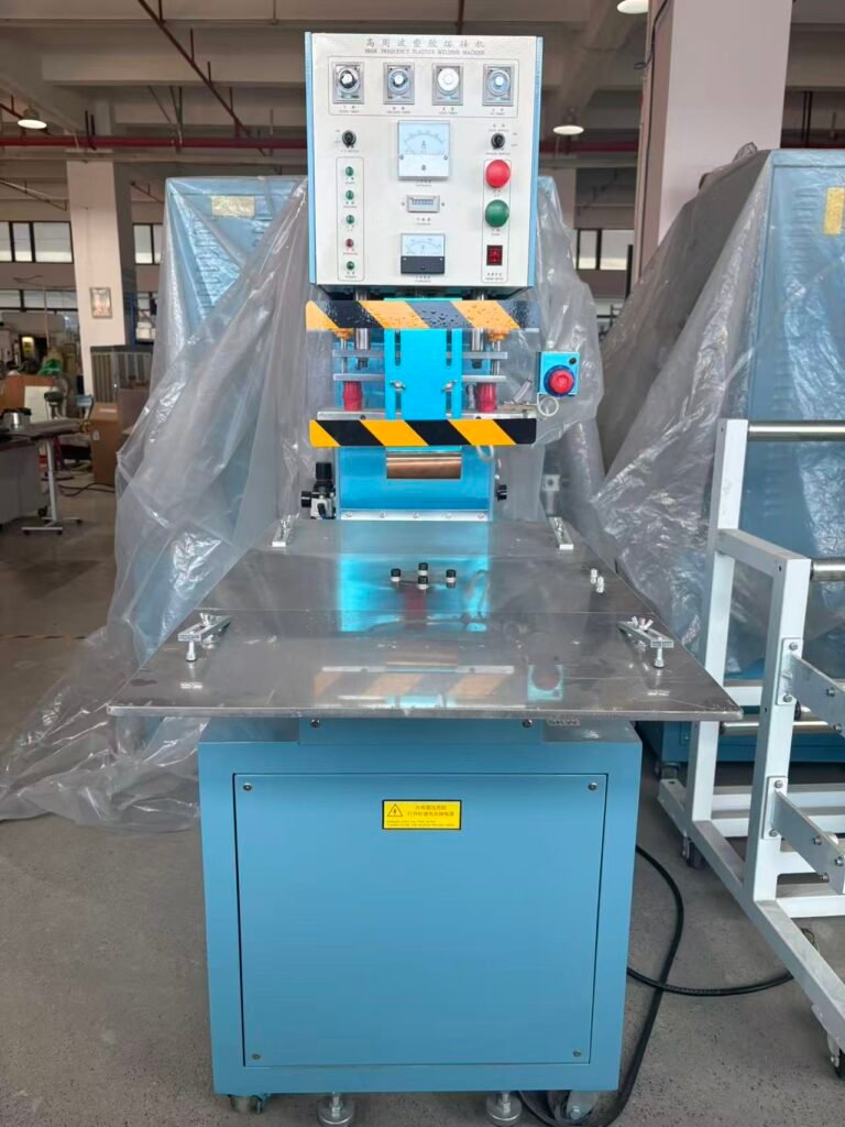
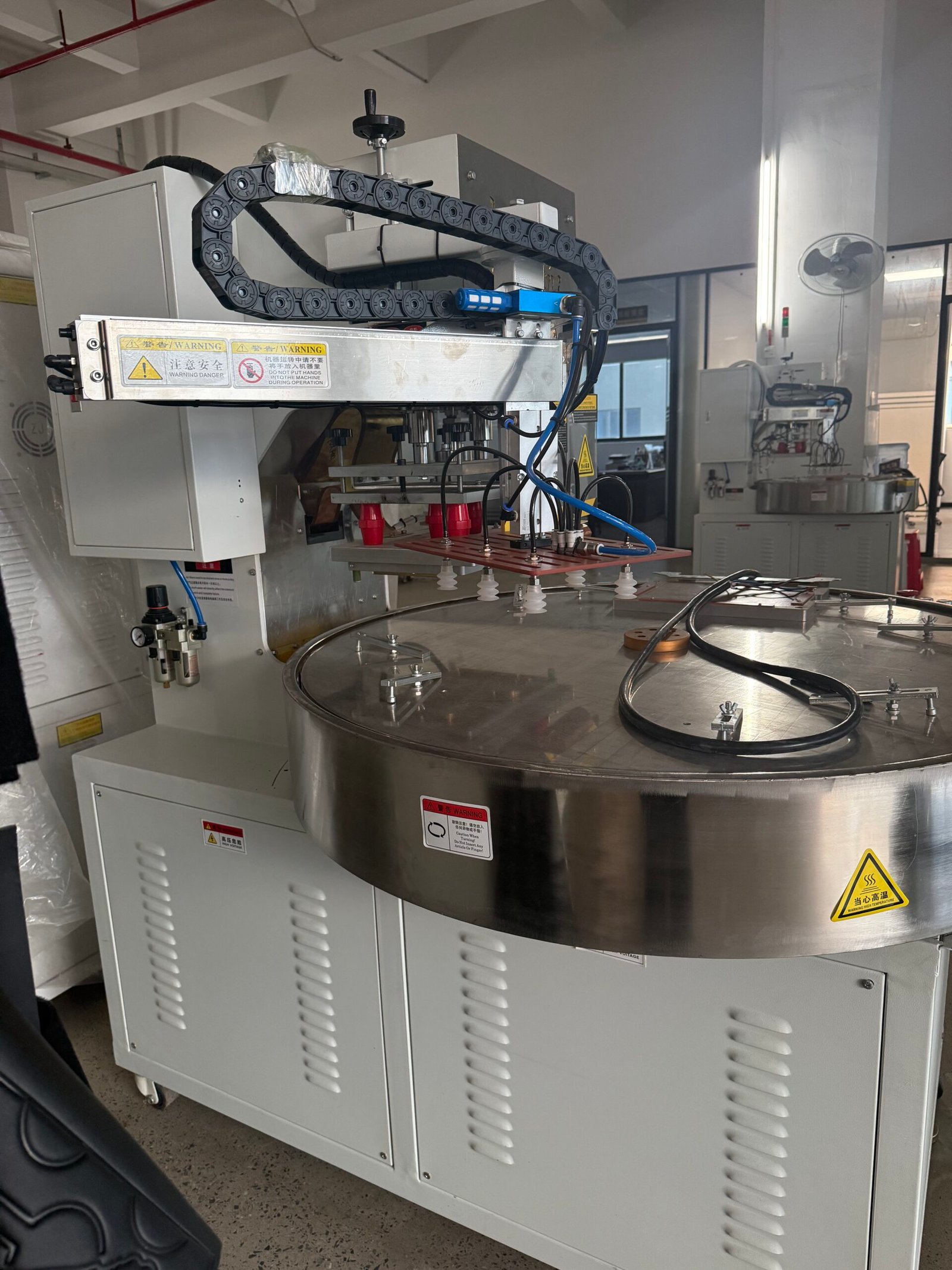
You commonly find this configuration on rotary HF welding machines and shuttle systems. On a rotary machine, the operator loads one station while the machine welds at another station. On a shuttle machine, the tray exchange and cycle trigger happen automatically after the operator activates the start. Semi-automatic operation drastically cuts operator skill requirements. It also eliminates the cycle-to-cycle parameter variation that plagues fully manual pressing.
Fully Automatic HF Welding: Automated Feed, Position, and Eject
A fully automatic high frequency welding machine adds mechanical feeding and ejection to the machine-controlled weld cycle. Parts enter the weld station through an automated feeder. Vibratory bowl feeders, conveyors, robotic arms, or magazine feeders deliver components without any manual handling between cycles.
Once inside, mechanical stops or vision-guided actuators position each part precisely within the die. The machine welds it and then ejects the finished piece onto an outfeed conveyor or into a collection bin. The operator’s role shifts entirely. Instead of loading part by part, the operator now monitors the system, replenishes bulk material, and performs quality check sampling. One operator can oversee multiple automatic machines simultaneously. This shift fundamentally changes the labor cost calculation.
Integrated HF Welding Cells: Part of a Larger Automated Line
The highest level of HF welding production line integration places the machine as one station within a broader automated cell. Upstream equipment feeds parts directly into the HF welder. Cutting machines, thermoformers, or printing stations deliver components in sequence. Downstream equipment receives finished parts immediately after ejection. Vision inspection systems, leak testers, and packaging machines connect directly.
No manual transfer points exist between any of these stations. This kind of industrial HF welding automation is standard in medical bag manufacturing, blister packaging lines, and automotive interior component production. The HF welding station communicates with all upstream and downstream equipment through a shared PLC or factory network. It continuously adjusts its cycle timing to match the overall line throughput rate.
The Core Components of an Automated RF Welding System
Every automated RF welding system builds from a set of standard functional components. Understanding each one helps you evaluate supplier proposals and plan your integration requirements.
PLC Control System: The Operational Brain
The PLC functions as the operational brain. It executes the weld cycle sequence, monitors sensor inputs, manages interlock conditions, stores recipe parameters, and communicates with external equipment.
A PLC controlled HF welder stores multiple named recipes. Each recipe corresponds to one specific product. It contains the exact power level, weld time, cooling time, press force profile, and any application-specific timing sequences. Switching products requires selecting the correct recipe from the HMI panel. Operators do not manually adjust individual parameters. This system eliminates setup errors and makes changeovers dramatically faster.
The PLC also handles safety interlocks. If a sensor detects a missing part, a misaligned fixture, or an out-of-range parameter, the PLC stops the cycle instantly. This protective function proves essential in continuous-run automated systems. An undetected fault in one cycle can cascade into dozens of defective parts before a manual inspection ever catches it.
HMI: The Operator’s Window into the Machine
The HMI is the touchscreen panel that connects operators to the PLC. It displays current cycle status, active parameter values, alarm history, production counts, and the recipe selection menu. A well-designed HMI reduces training time significantly. It helps operators diagnose issues quickly without calling for engineering support every time.
For HF welding production line integration, the HMI must show more than just the welder’s status. It should display live data from upstream and downstream equipment. Operators monitoring the cell need to see conveyor speed, feeder fill level, and downstream equipment status on a single screen. This unified view gives them a complete picture of line health.
Automated Feeding System: Delivering Parts at Speed
The feeding system delivers parts to the weld station at the exact rate the machine can process them. The right design depends entirely on part geometry, material type, and required feed rate.
Vibratory bowl feeders handle small, rigid, consistently shaped parts perfectly. Blister shells, small PVC components, and formed packaging ride up the bowl track. The feeder orients them automatically and delivers them in a single-file stream to the weld station.
Conveyor-based infeeds manage larger or more fragile parts. A vibratory bowl would damage or tangle these components. Flat conveyor belts with guide rails deliver them in controlled orientation at adjustable speeds. Some systems use indexing conveyors. These stop-start belts advance one part into the weld position per cycle and hold steady until the cycle completes.
Robotic arms provide the ultimate in flexibility. A 6-axis robot picks parts from a bin, tray, or previous production station. It orients them precisely, places them into the weld fixture, and then removes the finished part after the cycle. Robot-based loading suits irregular shapes, heavy parts, and applications that demand placement accuracy beyond what mechanical stops can achieve.
Precision Fixture and Positioning System
Automated feeders deliver parts to the weld station, but the fixture positions them accurately within the die. Fixture design is critical. A part that arrives just 0.5 millimeters out of position produces a seam shifted by 0.5 millimeters. At high cycle rates, even tiny positional errors accumulate rapidly into significant reject rates.
Mechanical stops and registration pins provide the simplest positioning method. They suit parts that have consistent external geometry and can register against a fixed reference surface. Vision-guided positioning systems offer a more advanced solution. Cameras and image processing detect the actual part position in real time. The system then adjusts the pickup or placement mechanism accordingly. This approach handles the part-to-part variation that mechanical stops cannot accommodate.
Arc Detection and Automatic Parameter Adjustment
Manual machines rely on the operator to notice arcing and stop the cycle. Automatic high frequency welding machine designs cannot depend on human reaction. A fast-acting arc suppression circuit in a PLC controlled HF welder cuts HF power within milliseconds of detecting a spark event. It then logs the occurrence. If arcing frequency exceeds a preset threshold, the PLC halts the machine and triggers an alarm. It refuses to continue producing defective or damaged parts.
More advanced systems include automatic tuning circuits. These circuits continuously monitor impedance matching between the generator and the electrode. They adjust the matching network in real time to compensate for electrode temperature drift and material variation between batches. The result is consistent power delivery throughout an entire shift, without any operator intervention.
Outfeed and Ejection System
After the press opens, the finished part must leave the weld station and transfer to the next process. Several ejection mechanisms handle this task. Simple pneumatic air blasts blow small, lightweight parts off the lower table into a collection bin. Servo-driven pushers transfer parts onto an outfeed conveyor at a controlled, gentle rate. Robotic pick-and-place arms handle parts with maximum precision. They place finished components directly into inspection fixtures or packaging trays.
The ejection system must never damage the freshly welded seam. Parts ejected immediately after cooling must be structurally stable enough to survive the transfer force. If the required cycle rate constrains cooling time, the ejection method must be gentle. It must avoid deforming the partially cooled weld zone.
Integrating HF Welding With Upstream Equipment
An automatic high frequency welding machine rarely operates as an island. It receives parts from upstream processes and must synchronize perfectly with their output rates.
Thermoforming Lines
In blister packaging production, a thermoformer sits just upstream of the HF welding machine. It produces formed blister shells at a fixed rate. The HF welding station must consume these shells at the same rate. Alternatively, a buffer zone must absorb any minor rate mismatches. Conveyor-based transfer with a controlled buffer zone allows both machines to run at slightly different instantaneous speeds while maintaining overall line balance.
Cutting and Slitting Equipment
Some products start as roll stock. Medical film bags, PVC tarpaulin panels, and inflatable product components all begin this way. An upstream cutter or slitter pre-cuts the pieces before they reach the HF welding station. These cut pieces must arrive in consistent dimensions and correct orientation. An indexing conveyor or robotic transfer arm handles this transition seamlessly. A machine vision system can also verify part dimensions just before each weld cycle begins.
Printing and Labeling Stations
Certain products require printing or labeling before the final seal. In blister packaging, a printing station applies the backing card just before the HF sealing cycle bonds it to the blister. In medical bag production, pre-printed port labels are positioned on the bag film before the perimeter seal closes. Integrating these pre-weld assembly steps into the automated line demands precise synchronization. The printing or dispensing equipment must match the HF welder’s cycle timing exactly.
Integrating HF Welding With Downstream Equipment
Parts leaving the HF welding station need further processing. The automated line must transfer them efficiently to downstream stations without any manual handling.
Leak and Integrity Testing
Medical bags, inflatable products, and fluid containment components all require leak testing after sealing. Automated leak testers pressurize the sealed product and monitor for pressure decay. These units accept parts directly from the HF welder via conveyor transfer. They return a simple pass or fail result. This triggers automatic sorting: pass parts continue down the line, fail parts divert to a reject lane.
Integrating the leak tester with the HF welding PLC allows the system to correlate test results with specific weld cycle data. If a batch shows elevated failure rates, the system traces back to the weld cycle parameters active during those failing cycles. This traceability proves essential in regulated medical manufacturing environments.
Vision Inspection Systems
Camera-based inspection systems verify seam width, seam position, surface appearance, and dimensional compliance on every single part. They do not rely on statistical sampling alone. Machine vision inspection after HF welding catches die alignment drift, material thickness variation, and die surface contamination immediately. It stops defective parts before they reach the next production stage.
Integration with the HF welding PLC allows inspection results to feed back directly into the machine’s parameter management. A vision system that detects consistent seam width drift can trigger an automatic die position correction. It can also alert the operator to check electrode leveling, all without stopping production until the drift exceeds a defined tolerance limit.
Packaging and Counting Systems
Finished parts transfer from the HF welding cell to packaging equipment through a conveyor or robotic transfer. Blister heat sealers, cartoning machines, or flow wrappers receive the output seamlessly. The HF welding cell’s PLC communicates part counts and production status to the packaging equipment’s control system. Both sides run at synchronized rates without accumulating excess buffer inventory.
When Automation Is the Right Investment
Automation adds capital cost, integration complexity, and ongoing maintenance requirements. It pays off only when the production conditions truly justify it. Evaluating these conditions honestly prevents over-investment in capability you will never fully use.
Volume Threshold
A manually operated shuttle HF welding machine running two eight-hour shifts produces roughly 10,000 to 15,000 cycles per day on standard products. If your required output consistently exceeds this range, an automatic high frequency welding machine becomes financially compelling. The same holds true if meeting that output requires more operators than the manual approach can economically sustain.
Your break-even analysis should include several key factors. Compare the capital cost of the automated system against the cost of additional manual machines and operators. Factor in labor cost savings per shift. Account for the quality improvement value gained from reduced operator-dependent variability. Finally, include the cost of downtime required for integration, commissioning, and on-going maintenance of the automated system.
Labor Cost and Availability
The economics of automation shift dramatically based on your location. In markets where skilled manufacturing labor is expensive or difficult to retain, automation justifies itself at a much lower volume threshold. A factory in Germany or the United States may find automation economical at just 8,000 cycles per day. A factory in a lower-cost labor market may only see the economics work above 25,000 cycles per day. The difference in hourly labor cost drives this calculation.
Quality Consistency Requirements
Regulated production environments demand documented process consistency. Medical device manufacturing under ISO 13485 and pharmaceutical packaging under GMP fall into this category. Manually operated machines make this level of consistency difficult to achieve and even harder to prove. An automatic high frequency welding machine with PLC-logged cycle data, recipe management, and audit trail functionality supports validation requirements that manual operations simply cannot meet efficiently.
Product Stability
Automation delivers its best return on stable, long-running products. If your product mix changes frequently—different styles, sizes, or materials every week—the changeover complexity and tooling cost of a fully automated system can quickly erode the expected efficiency gains. High-mix, lower-volume operations are almost always better served by flexible semi-automatic configurations. Fully integrated automated cells work best for stable, high-volume product lines.
HF Welding Automation and Industry 4.0
Modern automatic high frequency welding machines connect to factory networks. They participate in wider manufacturing intelligence systems. This connectivity transforms the machine from a standalone production device into a data source that supports continuous improvement across the entire operation.
Real-Time Data Logging
Every weld cycle generates valuable data. This includes power output, weld time, cooling time, press force, electrode temperature, cycle count, and arc event frequency. An Industry 4.0-capable HF welding machine logs all of this data automatically. It timestamps each entry to the specific product batch and operator shift. This data remains accessible through the factory network in real time, not just through a local HMI panel.
Predictive Maintenance
Analyzing cycle data over time reveals equipment degradation patterns long before they cause a production failure. A gradual increase in arc event frequency indicates electrode contamination or die wear. A rising power demand for identical parameters points to generator component aging. Trending these indicators allows your team to schedule maintenance during planned downtime. This replaces the costly emergency response that happens when a machine fails mid-run.
Remote Monitoring and Diagnostics
Factory network connectivity allows engineers to monitor machine status and review cycle data from any authorized location. Remote diagnostics take this further. The machine supplier’s engineers connect securely to the machine’s PLC over the network. They can make parameter adjustments, install software updates, and diagnose faults without an on-site service visit. For automated production lines running multiple shifts, this capability dramatically cuts the downtime previously spent waiting for an engineer to arrive.
OPC-UA and Standard Protocol Integration
Industrial communication standards like OPC-UA, Profibus, and EtherNet/IP allow the HF welding machine’s PLC to exchange data directly with MES platforms, ERP systems, and other production line equipment. This happens without custom software development. When you specify an automated RF welding system, confirm that the machine’s PLC supports the communication protocols your factory already uses. Integrating a machine that relies on a proprietary protocol into a standard factory network adds significant cost and complexity that the supplier rarely mentions during the sales process.
Frequently Asked Questions
No universal threshold exists. The decision depends on local labor costs, product margins, and quality requirements. A practical starting point for analysis: if your production plan requires more than two full-time operators dedicated solely to manual HF welding for more than one shift per day, the economics of automation deserve serious evaluation. In regulated medical manufacturing, the quality documentation benefits of a PLC controlled HF welder may justify automation at even lower volumes.
Partially, in some cases. Adding a PLC controller and automated press actuation to a compatible frame and generator is possible. However, adding full automated feeding and ejection to a machine not originally designed for it usually costs more than replacing the machine with a purpose-built automatic unit. Always evaluate upgrade costs against new machine costs before committing to a retrofit.
Stored recipes allow the operator to select the correct parameter set for the new product on the HMI. The machine switches parameters immediately. Physical changeover—replacing dies, adjusting fixtures, reconfiguring the feeding system—takes longer and depends on the machine’s mechanical design. Quick-change die holders and modular fixture systems reduce this time. For systems with robotic loading, the robot program also switches to the new product’s pick-and-place routine.
Common protocols include OPC-UA, Profibus DP, EtherNet/IP, and Modbus TCP. OPC-UA is increasingly the default choice for new installations because it supports both data exchange and security management within a single standard. When specifying a new automated RF welding system, always confirm the machine’s supported protocols against your factory’s existing control infrastructure before you finalize the purchase order.
The arc suppression circuit monitors the electrical characteristics of the HF generator output in real time. A spark event produces a characteristic voltage spike. The circuit detects this spike and cuts generator power within milliseconds, a speed no mechanical relay or human reaction can match. The PLC logs the arc event with a timestamp and the cycle parameters. If arc frequency exceeds a configurable threshold within a defined number of cycles, the PLC halts the machine and raises an alarm rather than risk continuing production on a degraded process.