Shuttle High Frequency Welding Machine: Best Use Cases and Setup Tips
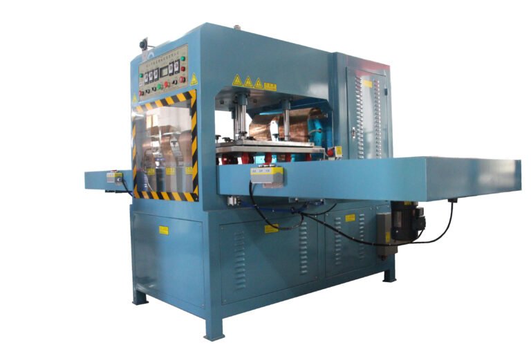
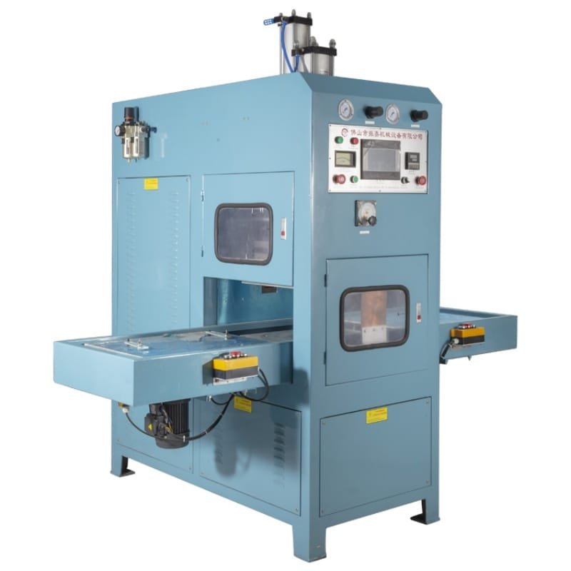
The shuttle high frequency welding machine is the production workhorse between the basic push plate and the high-volume rotary. It runs two trays instead of one. While one tray sits under the electrode and welds, the other sits in front of the operator for loading and unloading. The trays exchange positions after each cycle. The press almost never idles.
That simple mechanical change — parallel loading and welding — makes the double station HF welder the right choice for a wide range of medium to high-volume applications. It also makes it the dominant machine format in the medical bag industry, where precision positioning and process repeatability matter as much as output rate.
This article covers where the shuttle format performs best, what industries rely on it most, and how to dial in the key parameters to get clean, consistent welds from the first cycle onward.
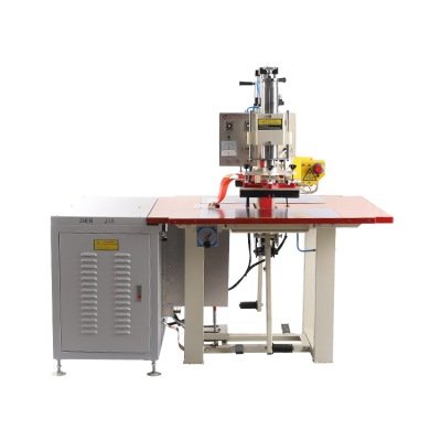
How the Shuttle Mechanism Works
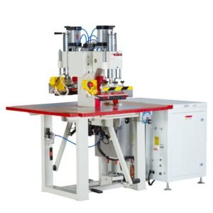
A shuttle HF welding machine uses a sliding tray system mounted on linear rails beneath the press. Most machines operate with two trays — front and rear, or left and right — though some configurations use a single large tray that travels in and out of position.
The sequence runs like this. The operator loads material onto the front tray, positions it carefully against the fixture or alignment pins, and activates the cycle. The front tray slides automatically into the weld position under the upper electrode. The press descends, the HF generator activates, and the weld cycle runs. At the same time, the rear tray — carrying the finished part from the previous cycle — slides out to the operator position for unloading and reloading.
When the weld and cooling cycle completes, the trays exchange positions again. The freshly loaded rear tray slides in and starts its cycle immediately. The previously active front tray comes out carrying the completed part. The press never stops to wait for the operator.
This overlap between loading and welding is what separates the shuttle format from a single-station push plate machine. The generator stays active for a much higher proportion of each working hour. Output climbs without requiring more floor space, more equipment, or faster operators.
Where the Shuttle HF Welder Performs Best
The shuttle format suits any application where product volume justifies the investment over a push plate machine, where product geometry requires precise flat-surface positioning, or where the weld cycle includes enough cooling time to make parallel loading genuinely useful.
Medical Bags and Fluid Pouches
Medical bag manufacturing is the most demanding and most common shuttle HF welding application. Blood bags, IV solution pouches, urine collection bags, colostomy bags, enteral feeding bags, and DVT compression sleeves all require the same combination of qualities: hermetic seals, consistent seam width, no contamination, and full process traceability.
The shuttle machine delivers all of these. The flat tray provides a stable, clean surface for laying out medical-grade PVC or EVA film in exact alignment before each cycle. The PLC-controlled weld time, cooling time, and power settings produce identical seams on every part. Because parameters are stored and recalled digitally, the process can be validated to IQ, OQ, and PQ standards — a requirement in regulated medical manufacturing environments.
Medical shuttle HF welders also handle products where tubes or connectors must be sealed into the bag wall during the weld cycle. These products require a two-stage sequence: first sealing the tube port, then completing the perimeter seam. Double-cycle shuttle configurations handle this without requiring two separate machines.
Automotive Interior Components
Car seat covers, door panel inserts, sun visors, trunk floors, and headrests all use PVC or PU materials that HF welding bonds cleanly and durably. Automotive applications favor the shuttle format for two reasons.
First, automotive components tend to be large. A door panel insert or a seat cover section may cover several hundred square centimeters of weld area. The shuttle machine’s large flat tray accommodates oversized dies without the constraints that a push plate’s fixed press geometry imposes. Some heavy-duty shuttle machines — such as the Zemat MEGA series — are built specifically for automotive and aerospace applications, with extra-large work surfaces, hydraulic presses for high cutting force, and heated electrode platens for consistent bonding of thick PU foam laminates.
Second, automotive production volumes are typically high and product runs are long. The shuttle format sustains high output rates with predictable, repeatable results across multi-shift operations. Tolerance consistency matters when parts must fit precisely into vehicle assemblies.
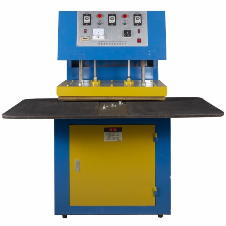
Packaging — Blister Packs and Medical Pouches
PVC blister packaging, clamshell retail packs, and medical device pouches all run efficiently on shuttle HF welders. The flat tray allows precise positioning of pre-formed blister shells against a flat backing card or film, which is essential for producing seals with consistent edge definition.
For blister packaging that requires a heated upper platen to pre-soften the rigid PVC or PETG before the HF cycle runs, shuttle machines with optional platen heating handles this cleanly. The temperature presets ensure each cycle starts from the same thermal baseline, which is especially important when processing harder, higher-Tg materials like APET.
Safety and Personal Protective Equipment
Safety vests, reflective warning jackets, high-visibility rainwear, and industrial gloves use PVC-coated fabrics that weld well under HF energy. These products often require multiple welds along shaped seams — collar edges, armhole borders, pocket openings — that need careful die positioning on each cycle. The shuttle tray provides a steady platform for managing these alignment requirements without rushing between cycles.
Rehabilitation and Medical Equipment
Air-inflated splints, pressure cuffs, patient positioning cushions, water mattresses, and medical-grade air bladders require the same airtight, watertight seals as medical bags but in thicker and more three-dimensional forms. Shuttle machines handle these products well because the flat tray supports the full footprint of the die during the press stroke, preventing uneven pressure across large or irregular weld areas.
How to Set Up a Shuttle HF Welding Machine: The Five Key Parameters
Getting clean, consistent welds from a shuttle HF welding machine requires setting five parameters correctly: press pressure, electrode leveling, HF power output, weld time, and cooling time. These five interact with each other. Changing one affects how the others perform. Always adjust them one at a time and run test welds after each change to isolate cause and effect.
1. Electrode Leveling
Level the electrode before adjusting any other parameter. An unlevel electrode applies uneven pressure across the die surface. On one side the material fuses properly. On the other side it sees too little force and forms a weak bond — or too much force and burns. Either outcome looks like a power or time problem when the real cause is mechanical misalignment.
Most shuttle machines include leveling screws or adjustment bolts at each corner of the upper electrode mounting plate. Use a flat reference surface and work systematically from corner to corner until the electrode contacts the lower tray surface with even force across its full width. Check leveling every time you install a new die, and recheck after any maintenance that involves removing or repositioning the press assembly.
2. Press Pressure
Pressure is the force the pneumatic or hydraulic cylinder applies to push the upper electrode into the workpiece. Higher pressure produces faster welds because it improves thermal contact and speeds molecular fusion. Pressure that is too low leaves an air gap between material layers, which concentrates the electromagnetic field in a small area, raises the risk of arcing, and produces a weak or incomplete seal. Pressure that is too high drives the electrode too deeply into the material before fusion occurs, which can crack brittle die edges or produce a weld that is too thin.
As a starting point, set pressure at a level that allows the electrode to sink smoothly into the material as it softens — without forcing it through before the fusion completes. On most shuttle machines the depth of sink control acts as a mechanical stop that limits how far the electrode can descend regardless of air pressure. Set the depth stop first, then adjust pressure to achieve smooth, consistent electrode travel within that range.
Typical pneumatic pressures for standard applications range from 2 to 5 bar, though this varies significantly between machine models and die sizes. Always consult the machine manufacturer’s specification sheet for your die surface area when establishing a starting pressure.
3. HF Power Output
Power output controls how much electromagnetic energy reaches the material per unit of time. More power heats the material faster. Too little power and the weld time must be long to achieve fusion — which increases the risk of die temperature buildup during sustained production. Too much power and the material overheats before sufficient pressure has been applied, causing surface burning, die sticking, or arcing.
Start at a low to medium power setting — roughly 40 to 60 percent of maximum — and increase gradually while running test welds. The goal is to find the lowest power setting that achieves full fusion within an acceptable weld time. Running at minimum effective power reduces electrode wear, minimizes arcing risk, and produces a more controllable process.
One practical complication: as the electrode heats up during a sustained production run, it pre-warms the material slightly before each cycle begins. This means the power setting that produces optimal welds when the machine is cold may be slightly too high after an hour of continuous operation. Good practice is to set power conservatively at start-up and monitor the first 20 to 30 cycles as the electrode reaches its working temperature. Reduce power slightly once equilibrium is reached. Most modern shuttle machines with automatic tuning systems manage this drift automatically.
4. Weld Time
Weld time is the duration the HF generator remains active during each cycle. It directly determines how much energy enters the material. Too short and fusion is incomplete. Too long and the material overheats, the surface burns, and the die may stick.
Set weld time based on material type and thickness. Thicker materials require more time. Materials with higher dielectric loss — such as flexible PVC — heat faster than materials with lower loss factors, so they require less time at equivalent power settings.
A useful rule of thumb from TWI’s HF welding handbook: cooling time should be approximately 20 percent of weld time as a starting baseline. If you set a 4-second weld time, start with a 0.8 to 1-second cooling time and adjust from there based on test results.
For products with complex or variable die geometries, consider running the machine in energy mode rather than time mode if your control system supports it. Energy mode terminates the weld when a preset amount of RF energy has been delivered — regardless of how long that takes. This compensates for part-to-part material variation and die temperature drift, producing more consistent welds across a long production run than fixed time mode.
5. Cooling Time
Cooling time is the period the press holds the electrode in contact with the welded material after the HF generator switches off. The electrode acts as a heat sink, drawing thermal energy out of the freshly fused material. Holding pressure during cooling allows the weld to solidify uniformly before the press opens.
Cooling time that is too short releases the material before it has fully solidified. The joint deforms slightly under the residual heat, producing a weld that looks superficially complete but has lower peel strength and is more prone to failure under stress. In medical applications this is a critical concern — bag seams must maintain integrity under the hydraulic pressure of filling and the mechanical stress of handling.
Cooling time that is excessive wastes production time without improving weld quality. The material solidifies well before the press opens, and the additional hold period contributes nothing.
In practice, cooling time requirements increase during sustained production because the electrode retains heat from successive cycles. A cooling time that worked correctly at start-up may become insufficient after an hour of continuous operation. Monitor weld quality throughout a shift — not just at the beginning — and increase cooling time incrementally if weld integrity declines as the electrode warms.
Product
Operating the Shuttle: Practical Tips for Consistent Results
Warm up the machine before the first production cycle. Run the generator at low power for two to three minutes before starting the shift. This brings the electrode to a stable working temperature and reduces the variability that cold-start cycling introduces into the first batch of parts.
Run test welds on scrap material at the start of each shift. Electrode temperature, room temperature, and material humidity all affect how the first cycles of a shift perform. Test welds confirm that stored parameters still produce acceptable results under current conditions before committing production material.
Clean the electrode daily. Carbon deposits from PVC outgassing accumulate on the electrode surface over time. This buildup concentrates the electromagnetic field in uneven patterns, increasing the risk of localized arcing and producing inconsistent seam profiles. Wipe the electrode surface with a clean cloth at the start and end of each shift. For heavier buildup, use a soft brass brush — never steel, which leaves conductive residue.
Check die alignment after every tooling changeover. When you swap dies for a different product, the new die may not seat identically to the previous one. Re-verify electrode leveling, re-check the depth stop, and run at least five test welds before committing to a full production run.
Monitor tray travel smoothness. The shuttle mechanism relies on clean linear rails and properly lubricated bearing surfaces. If the tray hesitates or catches during the exchange motion, the timing of weld cycle initiation becomes inconsistent — and with it, the weld quality. Inspect and lubricate the rail system monthly as part of the standard maintenance schedule.
For medical applications, document every parameter change. Regulatory compliance for medical device manufacturing requires a documented weld process with evidence that the validated parameters were maintained throughout production. Modern shuttle machines with PLC data logging capture weld time, power, and cycle count automatically. If your machine does not have this capability, maintain a paper log. Any deviation from validated parameters requires a process re-qualification step before production resumes.
Frequently Asked Questions
What is the difference between a single-station and a double station HF welder?
A single-station machine has one tray. The operator loads, welds, and unloads at the same position — always in sequence. A double station HF welder has two trays. One welds while the other loads. Because these actions overlap, the press runs almost continuously and output per hour climbs significantly compared to a single-station machine processing identical products.
Why do medical manufacturers prefer the shuttle format over push plate or rotary machines?
The shuttle provides a stable, flat loading platform with precise alignment control — essential for products like blood bags and IV pouches where die positioning must be exact on every cycle. The format also supports process validation requirements more naturally than a rotary machine, where loading across multiple stations introduces more operator variability. Shuttle machines are also easier to clean and inspect between batches, which matters in regulated production environments.
How long should cooling time be relative to weld time?
A widely cited starting guideline is approximately 20 percent of weld time — so a 5-second weld time suggests roughly a 1-second cooling time as a baseline. This ratio increases for thicker materials and for products with larger thermal mass. Always verify by testing: the weld should be fully solidified with no surface deformation when the press opens. Increase cooling time if any softness or distortion is visible after release.
Can I use a shuttle HF welder for products that need a heated platen?
Yes. Many shuttle machines offer optional heated electrode platens with programmable temperature presets. Heated platens are used for welding rigid PVC, PETG, and thick PU foam laminates that benefit from pre-warming before the HF cycle activates. Not all shuttle machines include this feature as standard — confirm with the manufacturer if your application requires it before purchasing.
What power range do I need for a shuttle HF welding machine?
Power requirements depend on die surface area and material thickness. As a rough guide, a 5 kW machine suits small to medium medical bag applications with die areas up to approximately 140 cm². An 8 kW machine handles most standard blister packaging, stationery, and mid-size medical products. Machines at 12 to 15 kW handle large automotive interior components and products with thick PU foam layers. Heavy-duty shuttle machines for large-area automotive and industrial applications may run at 20 to 30 kW with hydraulic press systems.
How often should I change the parameters stored in the machine’s recipe system?
Stored recipes should remain unchanged once validated for a specific product and material batch. Changes are warranted when switching to a different material grade, a different material supplier’s film, or a different die. For medical applications, any parameter change that falls outside the validated range triggers a formal requalification process. For non-regulated applications, run at least ten test welds after any recipe adjustment to confirm the new settings produce consistent, acceptable weld quality before returning to full production.